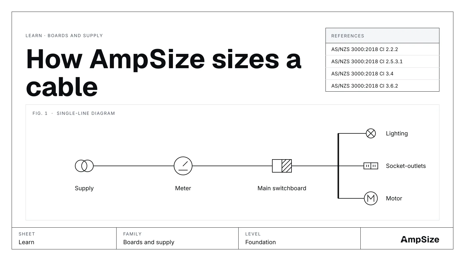
A cable size is the end of a chain of checks. Each check has a page here. This page sets the order. Follow it from the load to the certificate.
Step 1: find the load
Start with the current the circuit must carry. For one appliance it is on the label. For a whole installation it is the maximum demand.
Read Maximum demand and diversity. Then try Domestic maximum demand with Table C1 and Maximum demand per phase on a three‑phase supply.
Step 2: order the three currents
The load current (IB), the device rating (IN) and the cable capacity (IZ) must sit in that order. Work them in that order.
Read IB ≤ IN ≤ IZ. The guide What size breaker for 4 mm² cable shows the rule on one cable.
Step 3: find the capacity
Pick a tabulated rating. Then apply the correction factors for ambient temperature, grouping, soil and depth.
Read Current-carrying capacity and derating. The guides Tables 4 to 21 and Tables 22 to 29 cover the data.
Step 4: check the voltage drop
A cable that carries the current can still drop too much voltage. Long runs fail here first.
Read Voltage drop basics. The guides Clause 3.6.2 and the mV/A·m method give the limit and the method. Cable size for an estimate shows how length moves the size.
Step 5: check the earth fault loop
The device must open fast enough on an earth fault. The loop impedance decides that.
Read Earth fault loop impedance and disconnection time. The guide Table 8.1: maximum Zs explained gives the limits. Earthing conductor size sizes the earth.
Step 6: check the fault withstand
The cable must survive the fault until the device opens. That check uses the fault current, the time and the k factor.
Read Short-circuit withstand and the k factor. The guide Table 52: k factor has the data.
Step 7: test and certify
Test the finished circuit. Then record it.
Read Testing to Section 8 and Who may do electrical work in NZ. The test results tool checks measured values against the expected ones.
One circuit through the checks
Take a 32 A single‑phase circuit at 230 V. The power factor is 1. The run is 40 m. The ambient is 40 °C. Cables touch on a surface. The cable is multicore copper with PVC insulation. The device is a 32 A curve C breaker. Ze is 0.35 Ω.
The tool first applies a derating factor of 0.88 for the ambient. The required tabulated current is 36.36 A. It selects 6 mm².
- Derated capacity: 36.96 A, so IB ≤ IN ≤ IZ holds
- Voltage drop: 4.17 %, close to the 5 % limit
- Earth fault loop impedance: 0.86 Ω
- Earth conductor: 2.5 mm²
The tool warns that the drop is close to the limit. Capacity, drop and loop all pass. Each has a small margin.
Open the cable size tool with this circuit.
Now add a prospective fault current of 3 kA and a clearing time of 0.1 s. The fault withstand check controls the result. The size becomes 10 mm². The earth conductor becomes 4 mm².
Open the cable size tool with the fault check.
This is the point of the order. A cable that passes the first checks can still fail a later one.
Check a cable you already have
The same checks run in reverse for an existing circuit. Read Checking an existing circuit.
This page is a design aid. Verify every value against the current edition of the standard.
See also: Cable size for a 32 A single‑phase 25 m run, Submain cable size for 3‑phase 100 A over 60 m and Three circuits in a hot ceiling: correction factors.