

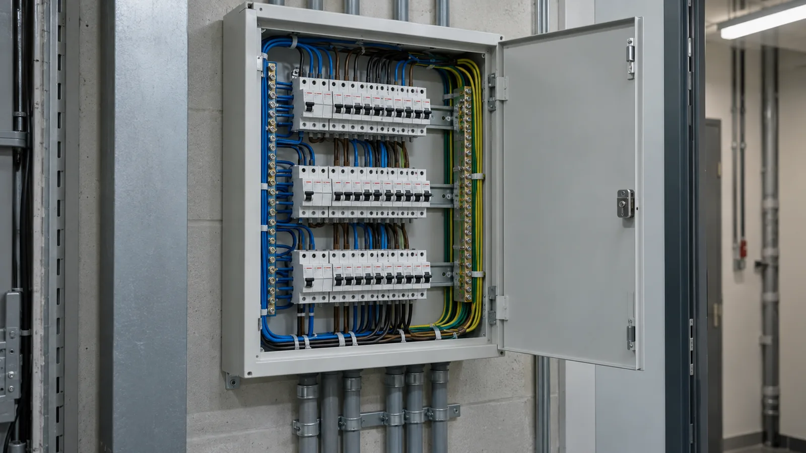
Three currents decide whether a protective device and a cable belong together. They are usually written IB, IN and IZ, and the rule is that they line up in that order.
The three currents
IB is the design current. The current the circuit is expected to carry in normal use. It comes from the load, not from the cable and not from the breaker.
IN is the nominal rating of the device. The current the breaker is rated to carry continuously. It has to be at least IB, or the breaker trips on normal load.
IZ is the current-carrying capacity of the cable, after derating. The tabulated rating for the conductor, reduced by every factor that applies to the route: ambient temperature, grouping, soil and burial depth.
The rule is IB ≤ IN ≤ IZ. Cl 2.5.3.1 is where the second half of that chain lives: the device rating must not exceed what the cable can carry.
Why the order is the whole point
If IN is below IB the circuit is unusable. If IN is above IZ the cable is unprotected: a current that would overheat the conductor can flow for a long time without the breaker seeing anything unusual. The breaker only protects the cable when it opens before the cable is damaged.
The awkward case is the middle one. A 32 A breaker on a cable that carries 30 A after derating looks fine on a nameplate and fails the rule. The cable is the part that burns.
A worked circuit
Take the 32 A single-phase circuit from the cable size guide. 230 V, 25 m, multicore copper PVC enclosed in air, 35 °C ambient, two circuits grouped, 32 A curve C device.
- IB is 32 A.
- IN is 32 A.
- IZ depends on the size chosen.
The 6 mm² conductor is tabulated at 38 A in this method. On its own it derates by 0.94 for ambient and gives an IZ of 35.72 A, which covers the 32 A device. Put the second circuit beside it and the grouping factor of 0.8 applies as well, and the IZ no longer reaches 32 A. The 10 mm² conductor is tabulated at 50 A and derates by both factors to an IZ of 37.6 A.
So the chain reads 32 ≤ 32 ≤ 37.6. It holds on 10 mm², and the tool reports that size.
Notice where the derating sits. It changes IZ, never IB and never IN. A hot, crowded route does not change the load or the breaker; it shrinks what the cable can carry.
Two checks that sit beside the rule
Fault withstand. IB, IN and IZ are about sustained current. A short circuit is different: a very large current for a very short time. The conductor has to survive the energy the device lets through before it opens. That check uses the fault current, the clearing time and the k factor for the conductor, and it is set out in Cl 5.3 of AS/NZS 3008.1.2:2017.
Disconnection time. The device also has to open fast enough on an earth fault, which is the loop impedance check. A device can satisfy IB ≤ IN ≤ IZ and still be wrong for the circuit because the loop is too long.
A habit worth keeping
Work the three currents in order, every time: load first, then device, then cable. Choosing the breaker from the cable, or the cable from the breaker, is how the middle case slips through.