

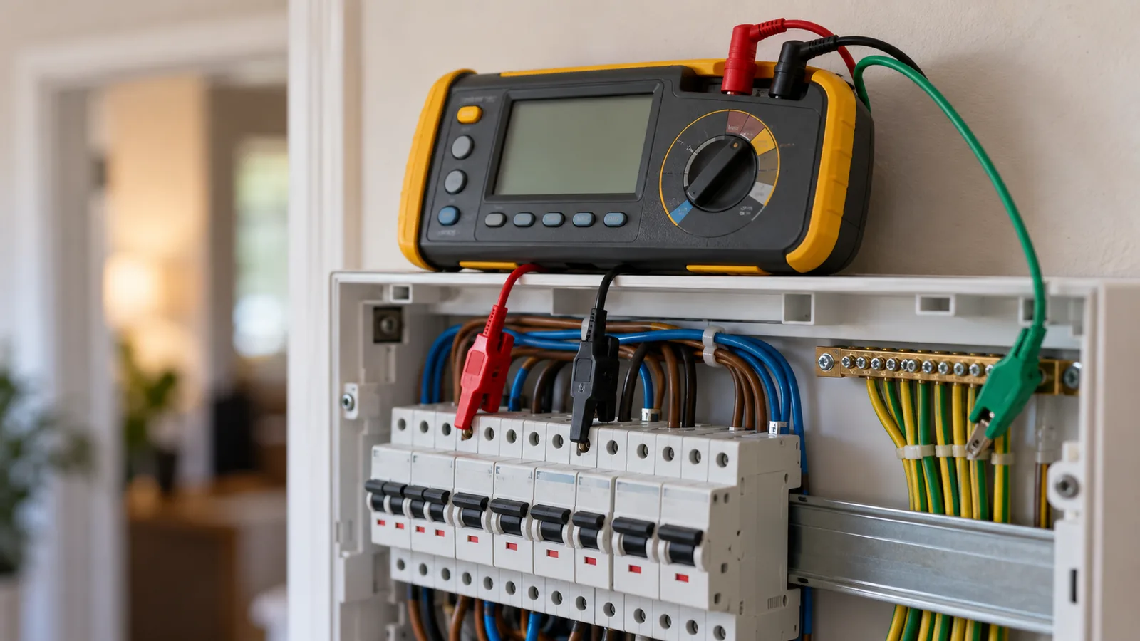
An earth fault has to draw enough current to operate the protective device, and it has to do that quickly. Both halves depend on one quantity: the impedance of the loop the fault current follows.
The loop
The MEN system gives a fault current a metallic path home. From the transformer the current runs along the active conductor to the fault, then back along the protective earth conductor to the MEN link, and through the supply neutral to the source. Every part of that path has impedance.
Zs is the impedance of the whole loop measured at the fault. It splits into two parts.
Ze is the external part. Everything upstream of the origin of the installation: the supply transformer, the network conductors and the consumer mains. Ze is measured or supplied by the network, not calculated from the installation.
R1 + R2 is the internal part. R1 is the active conductor from the board to the fault. R2 is the protective earth conductor back. The two run the same route, usually in the same cable, and the earth conductor is often the smaller of the pair.
Zs is Ze plus R1 + R2. Cl 5.7.2 of AS/NZS 3000:2018 sets out the requirement the loop has to meet.
Ia: enough current
A circuit breaker has two operating regions. A small overload takes the thermal element, and that is slow. A large current takes the magnetic element, and that is close to instantaneous.
Ia is the current that operates the magnetic element within the required time. It is a multiple of the device rating, and the multiple depends on the trip curve. A B curve device needs the smallest multiple, C needs more, and D needs more again. Table 8.1 of AS/NZS 3000:2018 holds the maximum Zs that follows from each device and curve.
The logic runs backwards from Ia. The loop has to be low enough in impedance that the fault current reaches Ia. A high Zs starves the fault, the magnetic element never sees enough current, and the thermal element takes over. The circuit then clears in seconds or minutes instead of a fraction of a second.
Two disconnection times
AS/NZS 3000:2018 sets two disconnection times, and Cl 5.7.4 states which one applies. The shorter time applies to final subcircuits, where a person is likely to be holding the faulty equipment. The longer time applies to distribution circuits, such as submains, where the exposed metal is inside a board.
Table 8.1 and Table 8.2 hold the maximum Zs values for the two cases. A circuit that fails the final subcircuit column may still pass as a distribution circuit. The clause, not the preference of the designer, decides which column applies.
A worked circuit
Take a 230 V final subcircuit protected by a 32 A curve C breaker. The external loop impedance is 0.35 Ω. The cable runs 30 m with a 4 mm² active conductor.
The tool sizes the protective earth conductor from Table 5.1 of AS/NZS 3000:2018 and gets 2.5 mm². It reads the resistance of the active and earth pair at operating temperature as 14.62 Ω/km, which over 30 m gives an R1 + R2 of 0.44 Ω.
Zs is then 0.79 Ω. The maximum permitted Zs from Table 8.1 is 0.96 Ω, so the circuit passes. The prospective earth fault current is 291.66 A.
The tool also reports a maximum length of 41.61 m. That is how far this cable and this device can run before Zs reaches the limit.
What the margin is worth
0.79 Ω against 0.96 Ω is not a large margin, and every term in it can move.
Ze changes with the network. A figure supplied for a design is a nominal value, and the measured value on the day can be higher. R1 + R2 rises with conductor temperature, which is why the tool uses the operating temperature rather than 20 °C. Adding length to the run, or extending the circuit later, raises it further.
The earth conductor usually dominates. It is the smaller of the pair, so its resistance per metre is the larger. Increasing the active size on its own moves Zs less than people expect.
Calculated Zs and measured Zs
Cl 8.3.9 of AS/NZS 3000:2018 covers the earth fault loop impedance test. The calculation and the test answer the same question from opposite directions.
The calculation runs before the cable is pulled, so it decides the size and the length. The test runs on the finished installation and confirms what was built. The two rarely agree exactly, because the calculation uses tabulated conductor data and a nominal Ze, and the tester measures the real loop at the temperature of the day.
A measured Zs well above the calculated value is worth chasing. A loose earth connection, a longer route than the drawing showed, or a higher Ze than the network quoted all show up that way.
Three habits worth keeping
Take Ze from the network or a measurement. A guessed Ze makes every number downstream a guess.
Check the curve before the size. Moving from a C curve to a B curve raises the permitted Zs without changing a single conductor.
Check Zs at the far end. The loop is longest at the last outlet on the circuit, not at the board.
This page is a design aid. Verify every value against the current edition of the standard.