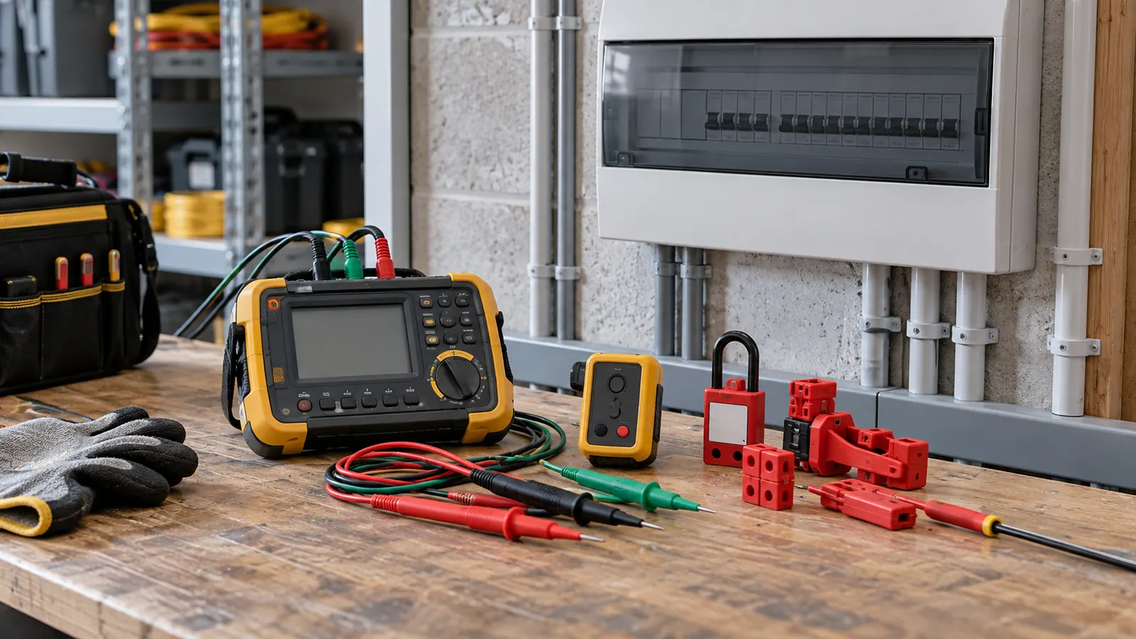
Section 8 of AS/NZS 3000:2018 turns a design into evidence. Each test answers one question about the installation, and the questions run in an order. A later test can damage equipment if an earlier one has not passed.
The sequence and the question each test answers
Continuity of the earthing system, Cl 8.3.5. Does every exposed conductive part connect back to the main earth bar. This is the first test because every later protective measure depends on it.
Insulation resistance, Cl 8.3.6. Is the insulation between live conductors, and between live conductors and earth, still intact. The test applies a d.c. voltage, so sensitive equipment comes out of circuit first.
Polarity and correct connection. Does the active land on the active terminal at every point. Switches in the neutral and crossed terminals both show up here.
Earth fault loop impedance, Cl 8.3.9. Will enough current flow on an earth fault to operate the protective device in time.
RCD operation, Cl 8.3.10. Does the residual current device trip, and does it trip inside the stated time.
Dead tests and live tests
Continuity, insulation resistance and polarity happen with the installation isolated. Loop impedance and RCD operation need the supply on. The order therefore runs dead first and live second. A live test on an installation that failed a dead test puts energy into a known fault.
Zero the test leads before a loop impedance reading. Lead resistance of a few hundredths of an ohm is a large share of a 0.8 Ω result. An unzeroed instrument reports its own leads as part of the loop.
Calculated Zs against measured Zs
The loop impedance tool gives the value a design predicts. The tester gives the value the finished circuit delivers. Compare the two and the difference tells a story.
Take a 20 A curve C final subcircuit. 230 V, 25 m of 2.5 mm² copper, an external loop impedance of 0.35 Ω at the origin.
The tool sizes the earth conductor at 2.5 mm², so the active and the earth run at the same size. It reads the conductor resistance and reactance at the operating temperature and gets 18.02 Ω/km for the pair. Over 25 m that is an R1 + R2 of 0.45 Ω.
Add the external part and the loop impedance is 0.8 Ω. The Table 8.1 limit for a 20 A curve C device is 1.53 Ω, so the circuit passes. The prospective fault current is 287.32 A, and the maximum length at the limit is 65.67 m.
Open the earth fault loop impedance calculator with these inputs.
Reading the gap between the two numbers
A tester reading close to 0.8 Ω confirms the design. A reading well above it points at a real fault. The usual causes are a loose terminal or a joint in the earth. A conductor smaller than the drawing does it. So does a longer route than the one priced.
A reading well below it usually means the external impedance on site is lower than the 0.35 Ω assumed. That is common. It does mean the margin belongs to the network, not to the design. A design that only passes because the measured Ze came in low will fail when the network changes.
Two further points move the numbers. The tool works at the conductor operating temperature, which is the hot case. A tester measures a cold installation, so a measured value below the calculated one is expected. Table 8.2 covers the alternative route, where a maximum length replaces a maximum impedance.
Records and instruments
Reg 63 of the Electricity (Safety) Regulations 2010 concerns testing before connection. Cite the regulation number and read the current reprint for what it requires.
AS/NZS 3760:2010 covers in-service inspection and testing of equipment already in use. Cl 2.3.3.1 sits in that sequence. It is a different document from Section 8 and it answers a different question. Section 8 tests the installation once, before connection. AS/NZS 3760:2010 tests appliances repeatedly, through their life.
Record the instrument, the range and the reading, not just a pass mark. A number written down can be compared at the next test. A tick cannot.
A habit worth keeping
Run the calculation before the visit, not after. Arriving with a predicted Zs of 0.8 Ω turns the test into a check of one number. Arriving with nothing turns every reading into a question about whether the design or the workmanship is at fault.
This page is a design aid. Verify every value against the current edition of the standard.