

A 6 mm² copper cable does not have one current rating. It has a rating for each way you install it, and that rating falls again for every condition that makes heat harder to shed. This page explains where the first number comes from and what reduces it.
Where the tabulated rating comes from
AS/NZS 3008.1.2:2017 Tables 4 to 21 list a current for each conductor size. That current is not a property of the conductor on its own. Each table covers one installation method and one set of reference conditions.
The reference conditions include an ambient temperature, a single circuit on its own, and a conductor operating temperature set by the insulation. A cable carries the tabulated current and settles at that operating temperature. Nothing in the table is a safety margin you can spend.
Change any reference condition and the listed current no longer holds. Derating factors correct the table for the route you are actually wiring.
The four factors the tool can apply
Cl 3.5.2 to Cl 3.5.5 of AS/NZS 3008.1.2:2017 set out the corrections. The cable size tool applies four of them.
Ambient temperature. A hotter surrounding air or soil leaves less room for the conductor to rise. The factor comes from Tables 27(1) and 27(2).
Grouping. Circuits laid together heat each other. Each extra circuit in the bunch cuts the factor further. The tool reads Tables 22, 25(1) and 25(2).
Soil thermal resistivity. Dry or stony soil carries heat away slowly. Table 29 gives the factor.
Burial depth. Deeper cable sheds heat more slowly. Tables 28(1) and 28(2) give the factor.
Each factor is a multiplier at or below 1. The tool multiplies them into one total factor, then multiplies the tabulated rating by that total. Cl 3.4 of AS/NZS 3000:2018 requires the corrected rating to carry the design current.
A worked route
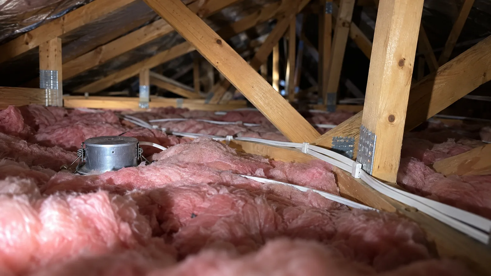
Take a single-phase 230 V circuit with a design current of 25 A over 20 m. The cable sits in partial thermal insulation. The ambient is 40 °C. Two other circuits run beside it, so the tool sees three grouped circuits. The device is a 25 A curve C breaker.
The tool reports the factors in order.
- Ambient derating factor: 0.88
- Grouping derating factor: 0.7
- Soil derating factor: 1
- Burial depth derating factor: 1
- Total derating factor: 0.616
From those it works back to the table. The required tabulated current is 40.58 A. That is the number to look up, not the 25 A of load.
The 6 mm² conductor is tabulated at 34 A in this method. After the factors it carries 20.94 A, which is below the design current. The 10 mm² conductor is tabulated at 46 A and carries 28.34 A after the same factors. The tool selects 10 mm² and reads it from Table 13.
Read the required current, not the load
The required tabulated current is the most useful figure on the result. It converts a site condition into a single lookup. Here the route costs the design a factor of 0.616, so a 25 A load needs a cable listed at 40.58 A or more.
That figure also shows the cost of a decision before you make it. Drop the group from three circuits to two and the grouping factor rises. The required current falls, and a smaller conductor may pass.
Install method is the first choice, not a correction
The method picks which table the tool reads, so it changes the starting number rather than the multiplier. A cable clipped in free air, a cable on a perforated tray, a cable enclosed in a wall and a cable surrounded by thermal insulation are four different tables for one conductor.
Site language and table language differ. A roof space with batts over the cable is thermal insulation, not enclosed in air. Choosing the method that matches the photograph, rather than the one that gives the answer you want, is the main way to keep a result honest.
What derating does not change
Derating moves the cable capacity only. The design current stays where the load put it. The device rating stays where the protection scheme put it. A hot, crowded route shrinks what the conductor can carry, and the ordering rule then decides whether the circuit still holds together.
Fault withstand is a separate check. Derating governs sustained current over hours. A short circuit is a very large current for a fraction of a second, and the conductor survives that on its cross-sectional area and its k factor.
Three habits worth keeping
Count every circuit in the bunch. The grouping factor counts circuits, not cables and not cores. A spare circuit installed today groups with the rest tomorrow.
Use the worst point of the route. A cable that runs 2 m through a 45 °C roof space derates for 45 °C. The cool part of the run does not average it out.
Record the factors, not just the size. The size is an output. The factors are what a reviewer checks when the load or the route changes.
This page is a design aid. Verify every value against the current edition of the standard.