

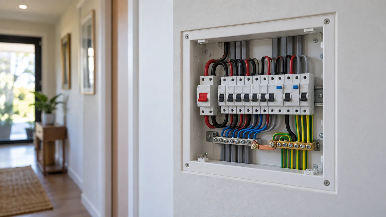
Every New Zealand installation uses the MEN system. The letters stand for multiple earthed neutral. The idea is simple: the neutral and the earth are joined at the main switchboard, and that joint is what makes an earth fault clear quickly.
The parts
The neutral bar. Every neutral conductor in the installation lands here.
The earth bar. Every protective earth conductor lands here.
The MEN link. A short, visible link between the two bars. It is fitted at the main switchboard only, and nowhere else in the installation. Cl 5.5 covers where it goes.
The main earthing conductor. It runs from the earth bar to the earth electrode.
The earth electrode. A rod or plate driven into the ground at the premises.
What the link does under a fault
An active conductor touches the metal case of an appliance. The case is bonded to the earth conductor. That earth conductor runs back to the earth bar, over the MEN link to the neutral bar, and out along the supply neutral to the transformer. The loop is closed through metal the whole way, so its impedance is low and the fault current is high.
High fault current is the point. It is what makes the circuit breaker open in a fraction of a second instead of holding a live case at a dangerous voltage.
Take the circuit from the loop impedance guide: 32 A curve C device, 25 m of 6 mm² copper, Ze of 0.35 Ω. The tool gives a loop impedance of 0.67 Ω and a prospective fault current of 343.8 A. The limit for that device is 0.96 Ω, so the circuit clears in time.
Break the metal path and none of that happens. A loose earth conductor, a missing bond or a disconnected MEN link turns a fast trip into a live enclosure. That is why the link is inspected and why earth continuity is tested before an installation is energised.
What the electrode does, and does not do
The electrode is often assumed to be the fault return path. It is not. Soil resistance is far too high to carry enough current to trip a breaker. The electrode is there to hold the earthing system near the potential of the general mass of earth, and to give the system a reference when the supply neutral is lost. The current that clears a fault goes over the MEN link and back along the neutral, not through the ground.
Cl 5.3 sets out what the earthing system has to achieve. Cl 5.7.4 is the check that matters at design time: the loop impedance has to be low enough for the device to open inside its disconnection time.
Why the link goes in one place only
A second neutral to earth connection downstream gives the neutral current two paths back to the supply. Load current then flows in the earth conductor as well as the neutral, all the time, not just under fault. That current is invisible on a normal test, it causes nuisance tripping of residual current devices, and it puts a small voltage on every earthed surface in the building.
This is also why the earth and neutral stay separate beyond the main switchboard, and why submains carry a separate earth rather than sharing the neutral.
What this means for design
Three things follow from the MEN system, and all three are checks the tools make.
Earth conductor size. The earth has to carry the fault current for as long as the device takes to clear it. It is sized from the active conductor size.
Loop impedance. The total impedance of the loop has to stay under the limit for the device. Length and earth size are the two levers.
Fault withstand. Both the active and the earth have to survive the fault energy. That is the short-circuit check.
Get those three right and the MEN system does the rest.