

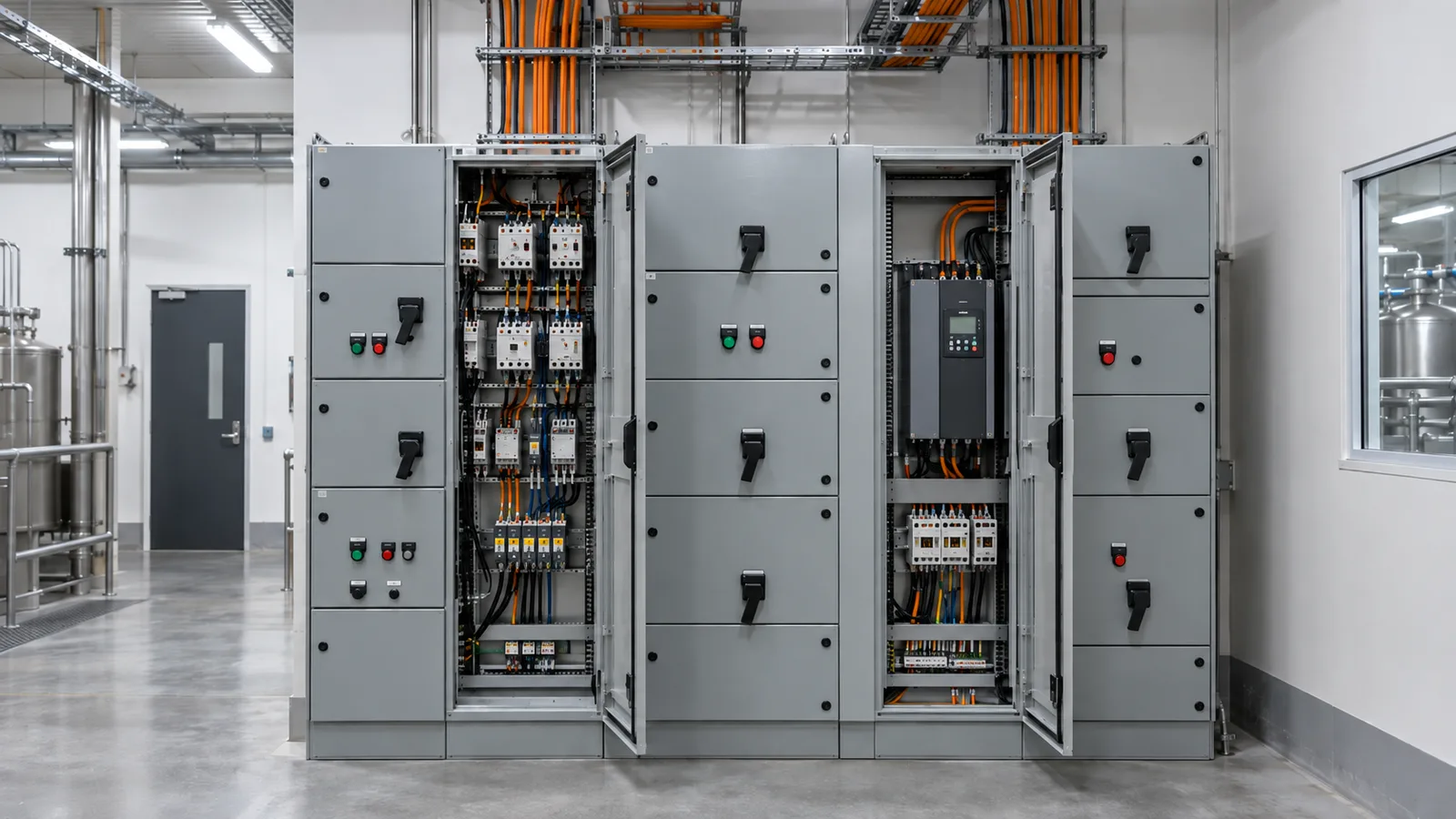
An industrial switchboard or a motor control centre carries three ratings that a domestic board does not. They are the short-circuit withstand, the form of internal separation, and the ingress protection. Each answers a different question, and each is chosen from the installation rather than from a catalogue.
Short-circuit withstand
This is the fault current the assembly can take, for a stated time, without coming apart. It is usually written as a current in kA with a duration, and it is verified by test rather than calculation. IEC 61439-1 Cl 9.3 sets out the short-circuit requirements for the assembly.
The number has to be at least the prospective fault current at the point where the board sits. If the network can deliver more than the board can take, the board is the weak point in the installation.
The conductors inside and downstream have to survive the same event, and that is a calculation. The fault rating tool works it. At 6 kA for 0.1 s on copper with PVC insulation, the k factor is 111 and the smallest conductor that survives is 17.09 mm². A 25 mm² conductor withstands 8.78 kA at that clearing time, so it has real margin. Cl 5.3 of AS/NZS 3008.1.2:2017 is the method.
Clearing time is the lever most people forget. Halve the time and the energy halves with it. A current-limiting device ahead of a long busbar run can save a conductor size.
Form of internal separation
Form describes how far the inside of the board is divided into compartments: busbars from functional units, functional units from one another, and terminals from everything else. A higher form means more barriers, and it is chosen for what has to happen while the board is live.
The question to ask is operational, not electrical. Does a fitter have to work on one starter while the rest of the board stays energised? Does a fault in one cubicle have to stay in that cubicle? Is the board in a plant that cannot be shut down for maintenance? Those answers pick the form, and the form drives the size and the cost of the enclosure.
Appendix K of AS/NZS 3000:2018 is the guidance on switchboard construction and the checks that go with it. Cl 2.5.4 covers the coordination of the devices inside.
Ingress protection
IP is two digits: the first for solid objects and dust, the second for water. A board in a clean plant room and a board on a dairy wash-down floor are not the same product. Wash-down, dust and outdoor exposure each push the second digit up, and a sealed enclosure then holds heat, which feeds straight back into the current rating of everything inside it. IEC 61439-1 Cl 8.2 covers the degree of protection provided by the enclosure.
Raising IP and then ignoring the temperature rise is a common and expensive mistake. Either derate what is inside, or add ventilation that keeps the IP rating.
Sizing what goes in the board
The load side of the board is ordinary work, and two tools cover most of it.
A 15 kW three-phase motor at 400 V, a power factor of 0.85 and an efficiency of 0.9 draws a full load current of 28.3 A. Its direct-on-line starting current is 169.81 A, and it develops 98.45 Nm at a shaft speed of 1,455 rpm on four poles. The starting figure, not the running one, sizes the starter and sets the volt drop seen by the rest of the board during a start.
For a non-motor load, the full load current tool gives 24.06 A for a 15 kW three-phase load at 400 V and a power factor of 0.9. The difference between the two figures is the motor efficiency and power factor doing their work.
The order to settle them in
Fault level first, because it decides whether the board can be there at all. Form next, because it decides the physical size. IP last, because it decides the enclosure and the heat inside it. Then size the outgoing circuits, and check every one of them against the fault withstand of its conductor.