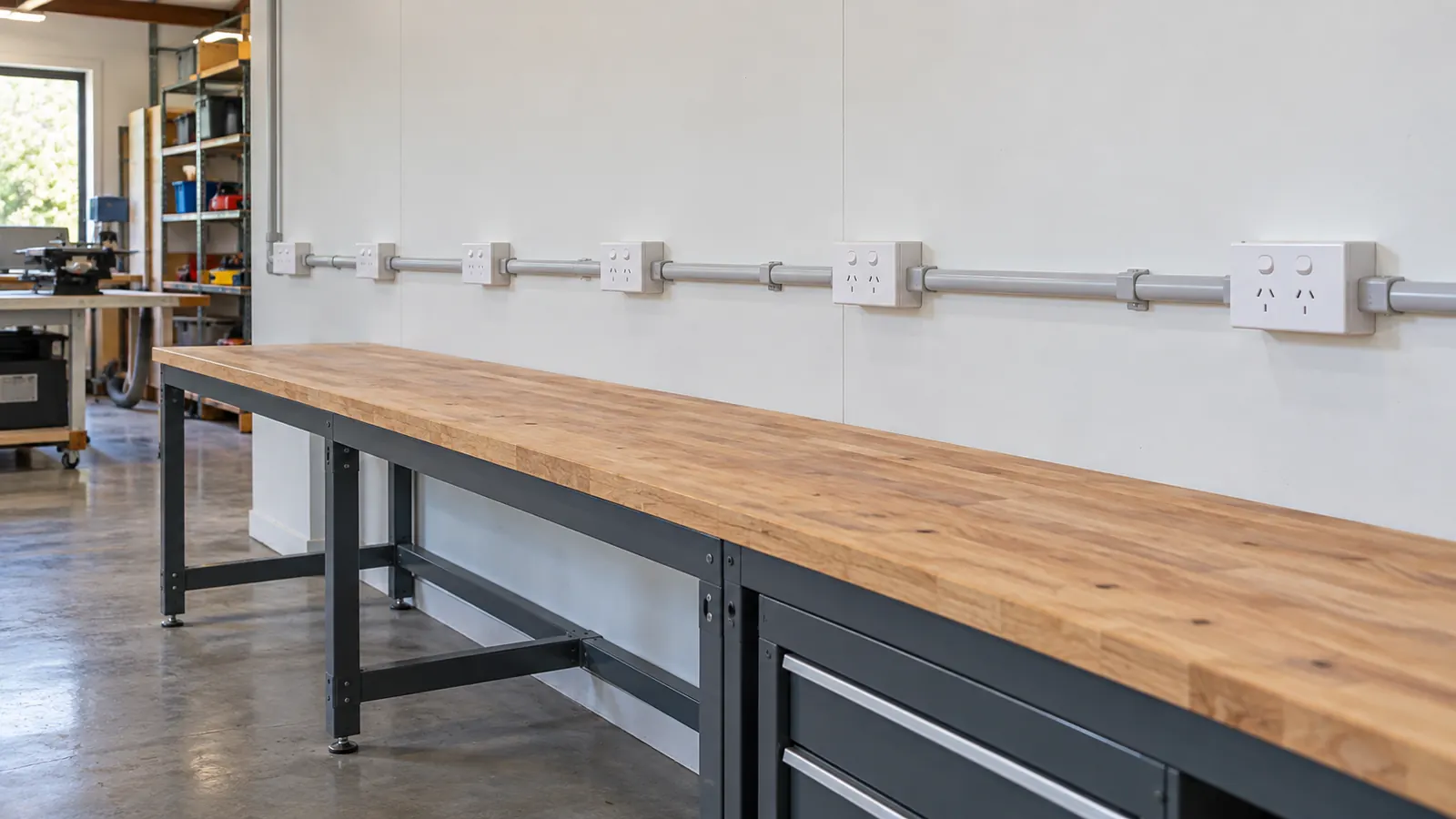
A socket circuit has to reach a workshop at the back of a site. The run is 40 m on 2.5 mm². The device is a 20 A curve C. The question is not whether the cable carries 20 A. It is whether the device still opens on an earth fault at the far end.
The question
A 20 A curve C circuit on 2.5 mm² has a maximum length. Past that length the earth fault loop impedance exceeds its limit. The tool returns a calculated Zs, the permitted Zs and that length.
The inputs
- External loop impedance Ze: 0.35 Ω
- Voltage: 230 V
- Device: 20 A, curve C
- Route length: 40 m
- Active conductor: 2.5 mm²
Ze covers everything upstream of the board: the supply transformer, the network cable and the consumer mains. 0.35 Ω is a common design assumption in New Zealand. Measure it where the result is close to the limit.
The clauses and the tables
Cl 5.7.4 of AS/NZS 3000:2018 sets the earth fault loop impedance requirement. Table 8.1 gives the maximum Zs for a device type and rating. Table 8.2 holds the disconnection times that Table 8.1 is built from. Table 5.1 sets the earth conductor size for a given active. Tables 34 and 35 of AS/NZS 3008.1.2:2017 hold the conductor resistance at the operating temperature.
The steps
The tool builds the loop from the outside in.
- Earth conductor size: 2.5 mm², from Table 5.1 for a 2.5 mm² active.
- R1 plus R2 per kilometre at the operating temperature: 18.02 Ω/km.
- R1 plus R2 over 40 m: 0.72 Ω.
- Earth fault loop impedance Zs: 1.07 Ω. That is Ze of 0.35 Ω plus the 0.72 Ω of cable.
- Maximum permitted Zs from Table 8.1: 1.53 Ω.
- Prospective fault current: 214.79 A.
The result
1.07 Ω against a 1.53 Ω limit. The circuit passes, and the tool reports no warnings.
The figure to write down is the maximum length: 65.67 m. On these inputs the circuit can reach that far before Zs meets the Table 8.1 limit. The 40 m run sits well inside that.
The prospective fault current of 214.79 A is the number behind the limit. A curve C device needs a multiple of its rating to trip in the magnetic region. 214.79 A is more than ten times the 20 A rating. The device therefore operates fast rather than on its thermal curve.
Three moves change the answer when a route runs past the maximum length.
Shorten the route. The loop grows with length, so this is the direct fix. A closer board or a better cable path both work.
Increase the conductor. 4 mm² lowers the ohms per kilometre, which lowers R1 plus R2 over the same distance. The earth conductor grows with the active under Table 5.1, so both halves of the loop improve.
Change the curve. A curve B device of the same rating trips at a lower multiple, so Table 8.1 allows a higher Zs. Check the load first. A curve B device on a circuit with inrush will trip on normal use.
Ze is the input worth checking on site. A measured Ze above 0.35 Ω eats the margin before the cable does anything. Compare the calculated Zs with the measured Zs during testing to Section 8.
This page is a design aid. Verify every value against the current edition of the standard.
See also: AS/NZS 3000 Table 8.1: max Zs by curve and rating, Earth fault loop impedance and maximum Zs and Loop impedance and disconnection time.