IEC 60364 is an international series of standards for low voltage installations in buildings. AS/NZS 3000, the Wiring Rules, is written to stay aligned with it. This page explains how the series is set out, what its earthing letters mean, and where the MEN system fits.
AmpSize holds one part of the series: IEC 60364-1:2001, the fourth edition of Part 1. Every IEC fact on this page comes from that part. AmpSize calculates to AS/NZS 3000, not to IEC 60364.
How the series is numbered
Annex A of Part 1 gives the numbering plan. The first digit of a part number gives its subject.
- Part 1 gives the fundamental principles, the assessment of general characteristics, and the definitions.
- Part 4 is protection for safety. Part 4-41 covers electric shock, 4-42 thermal effects, 4-43 overcurrent, and 4-44 voltage and electromagnetic disturbances.
- Part 5 is the selection and erection of equipment. Part 5-52 covers wiring systems and 5-54 covers earthing arrangements.
- Part 6 is verification.
- Part 7 has extra rules for special installations and locations. Examples are bathrooms, swimming pools, construction sites and marinas.
A clause number starts with the number of its part. Clause 131 is in Chapter 13 of Part 1.
The fundamental principles
Chapter 13 of Part 1 holds the fundamental principles. Clause 131 covers protection for safety. It names five hazards to protect against: electric shock, thermal effects, overcurrent, fault currents and overvoltage.
Clause 132 covers design. Clause 132.6 covers the cross-sectional area of conductors. In AmpSize, the cable size calculator does that step to AS/NZS 3000 and AS/NZS 3008.1.
The Preface of AS/NZS 3000:2018 states the alignment. Part 1 of AS/NZS 3000 keeps in line with IEC 60364 at the level of essential safety. Part 2 gives installation methods that are deemed to comply with Part 1.
Maximum demand
Clause 311 of IEC 60364-1 covers maximum demand and diversity. It is part of the assessment of general characteristics, before any cable is sized. AS/NZS 3000 gives its own methods, and the page on maximum demand and diversity explains them.
The system earthing types
Clause 312.2 names five types of system earthing: TN-S, TN-C-S, TN-C, TT and IT. Figures 31A to 31E draw the a.c. forms. Figures 31F to 31K draw the d.c. forms.
Each letter has one job.
- The first letter is the relation of the supply to earth. T means one point of the supply connects directly to earth. I means the supply is isolated from earth, or connects through an impedance.
- The second letter is the relation of the exposed conductive parts to earth. T means they connect to an earth of their own. N means they connect to the earthed point of the supply.
- The letters after the dash apply to a TN system. S means the neutral and the protective conductor are separate. C means one conductor does both jobs. That conductor is the PEN conductor.
So TN-C-S combines the two jobs in one part of the system and separates them in another part.
Where the MEN system fits
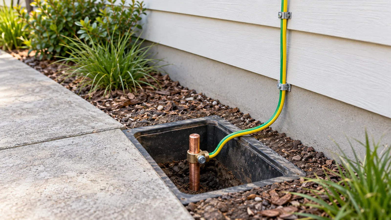
AS/NZS 3000:2018 Cl 5.1.3 covers the MEN earthing system. The notes to that clause say the IEC 60364 series calls it a TN-C-S system. They also say the two agree in principle but differ in detail.
The fit is simple. The supply network uses one conductor for the neutral and protective jobs. Inside the installation, the neutral and the earth are separate conductors. They join only at the MEN link on the main switchboard. The page on the MEN system explains each part.
Cl 5.1.4 covers other earthing systems. One example it gives is an installation to the IEC 60364 series with TN, TT or IT earthing.
A fault loop on a TN-C-S system
On a TN-C-S system, an earth fault current returns through metal all the way to the supply transformer. The path goes through the protective conductor, the MEN link and the supply neutral. So the loop impedance is low, and the protective device can clear the fault quickly.
Take a 20 A C curve circuit-breaker on 2.5 mm² copper, 20 m long, with a Ze of 0.35 Ω. The engine gives a loop impedance Zs of 0.71 Ω. The limit from AS/NZS 3000:2018 Table 8.1 is 1.53 Ω. The prospective fault current is 323.76 A, and the run can be 65.67 m before Zs reaches the limit. Open this loop in the calculator.
The loop impedance tool adds R1 + R2 to Ze. That suits a TN-C-S path. A TT system returns the fault current through the ground between two electrodes, so its loop impedance is much higher. The page on earth fault loop impedance explains the check and its time limits.
The d.c. forms
Figures 31F to 31K apply the same letters to d.c. systems. They show TN-S, TN-C, TN-C-S, TT and IT arrangements for a d.c. supply. They are relevant to battery and PV systems, where the d.c. side has its own earthing arrangement.
This page is a design aid. Verify every value against the current edition of the standard.