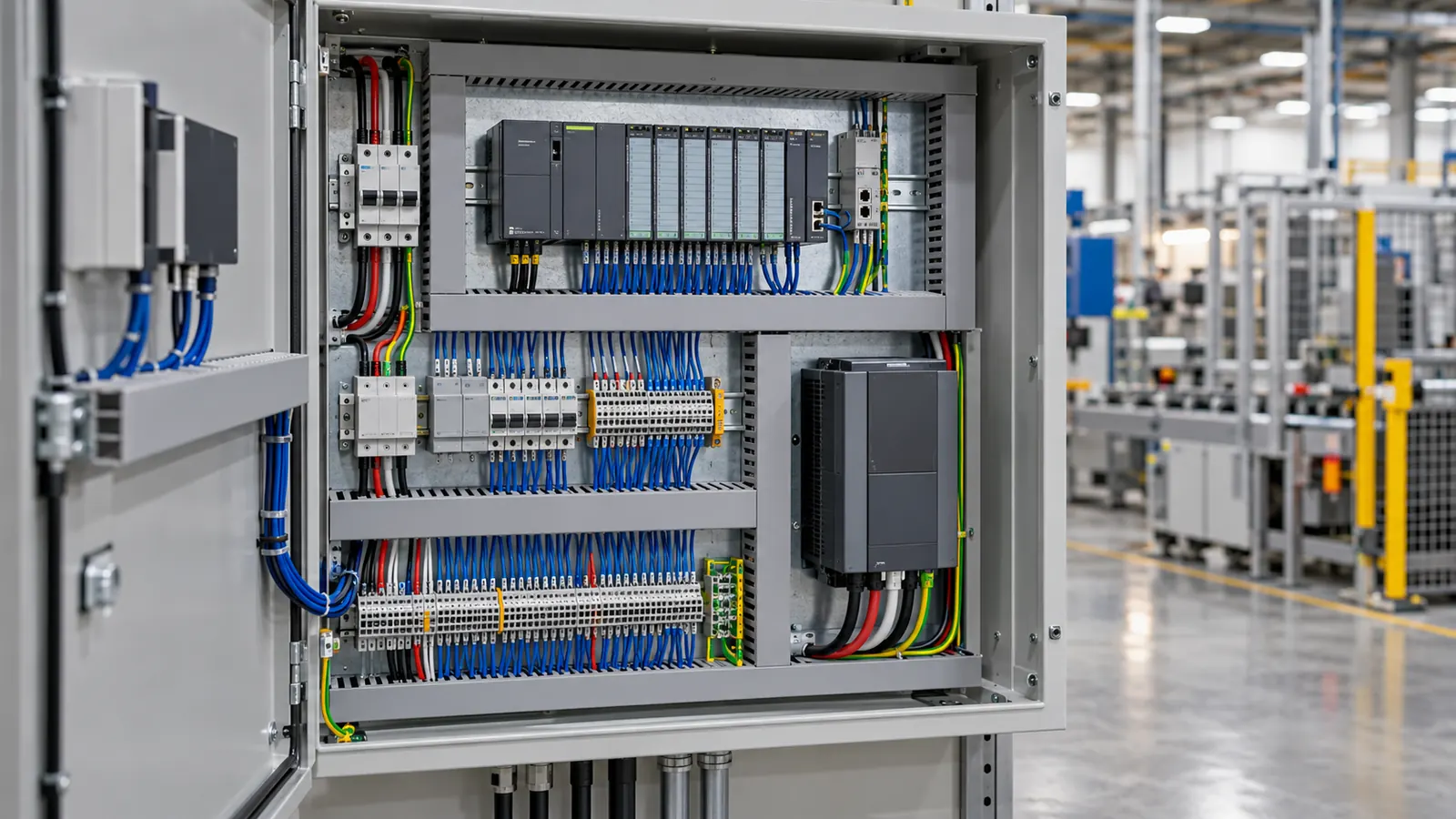
A control panel carries two systems in one enclosure. One runs at low voltage and switches power. The other runs at extra-low voltage and carries signals. Most panel problems come from the boundary between them.
Segregation
Cl 3.9.8 of AS/NZS 3000:2018 covers segregation of circuits in an enclosure. Table 3.3 sets out the separation arrangements.
The reason is interference as much as safety. A contactor coil dropping out puts a spike on anything that shares a duct with it. A variable speed drive output radiates across the width of the panel. An analogue 4-20 mA signal beside either of them picks up noise that looks like process data.
Three practices keep the noise out of the signals.
Separate ducts. LV power in one duct, ELV signals in another, with the drive output in a third where space allows.
Cross at right angles. Cross a power run and a signal run at 90 degrees. Do not run them together.
Earth the screen at the originating end. Where a screen needs earthing, earth it where the cable leaves the panel, at the panel earth bar. One earthing point leaves no closed path, so the screen carries no current. A second earthing point at the field end closes that path. For bus and network cables, check the device maker installation guide.
Terminals and numbering
IEC 61439-1:2020 Cl 8.4.3 covers accessibility and the arrangement of terminals inside an assembly.
The conventions that survive a fault-find at 2 am are the plain ones. One conductor per terminal. Ferrules on every conductor. The wire number matching the drawing, and the drawing matching the panel. Terminal rails grouped by function. The 24 V DC field terminals sit together, away from the 230 V control terminals.
Spare terminals cost almost nothing at build time. A panel with no spares forces the next change onto a doubled terminal or a junction box outside the enclosure.
Earthing the panel
Every door, gland plate and mounting plate is an exposed conductive part. Each one connects to the panel earth bar. Hinges are not a reliable path, so a door takes a bonding strap.
The panel earth bar connects back to the main earth bar of the installation. That connection is what makes the fault loop work. The MEN system returns the loop through the neutral at the main switchboard. A panel earthed only to a local rod has no low-impedance path back to the supply.
The 0 V rail of a 24 V DC supply is a separate matter. Cl 7.5.7 covers extra-low voltage circuits. Referencing the 0 V rail to earth is a design decision. Make it once for the whole panel, not per device.
The calculation people miss
An ELV circuit gets a 10 % drop allowance rather than the 5 % of an LV circuit. The allowance sounds generous. At 24 V it is 2.4 V, and a long field run spends it quickly.
Take a 24 V DC loop to a field device 150 m from the panel. It draws 0.5 A on 1.5 mm² copper.
The tool reports 33 mV/A·m for that conductor. Over 150 m at 0.5 A the drop is 2.48 V, which is 10.31 % of 24 V. The circuit fails the 10 % limit. The maximum length at the limit is 145.45 m.
Move to 2.5 mm² and the figure falls to 18.02 mV/A·m. The drop becomes 1.35 V, which is 5.63 %, and the maximum length rises to 266.37 m.
The conductor that carries a 0.5 A signal comfortably on current alone fails on voltage. This is the reverse of an LV power circuit, where capacity usually decides the size.
Open the voltage drop calculator with these inputs.
What the device needs at its terminals
The limit in the standard is not always the binding one. A transmitter rated for 12 V to 30 V tolerates a 2.4 V drop. A drive card or an electronic relay with a narrow input window does not.
Two habits keep this straight. Take the minimum operating voltage from the device data sheet. Set the limit in the tool to keep the device inside its window. Check the loop at its maximum current, not its idle current. A 4-20 mA loop draws most at full scale.
Backup supply
A 24 V DC panel often carries a battery for ride-through. The battery tool sizes it from a load list, a system voltage, a depth of discharge and an autonomy period. Set the inverter efficiency to 1 for a straight DC panel, because no inverter sits in the path.
This page is a design aid. Verify every value against the current edition of the standard.