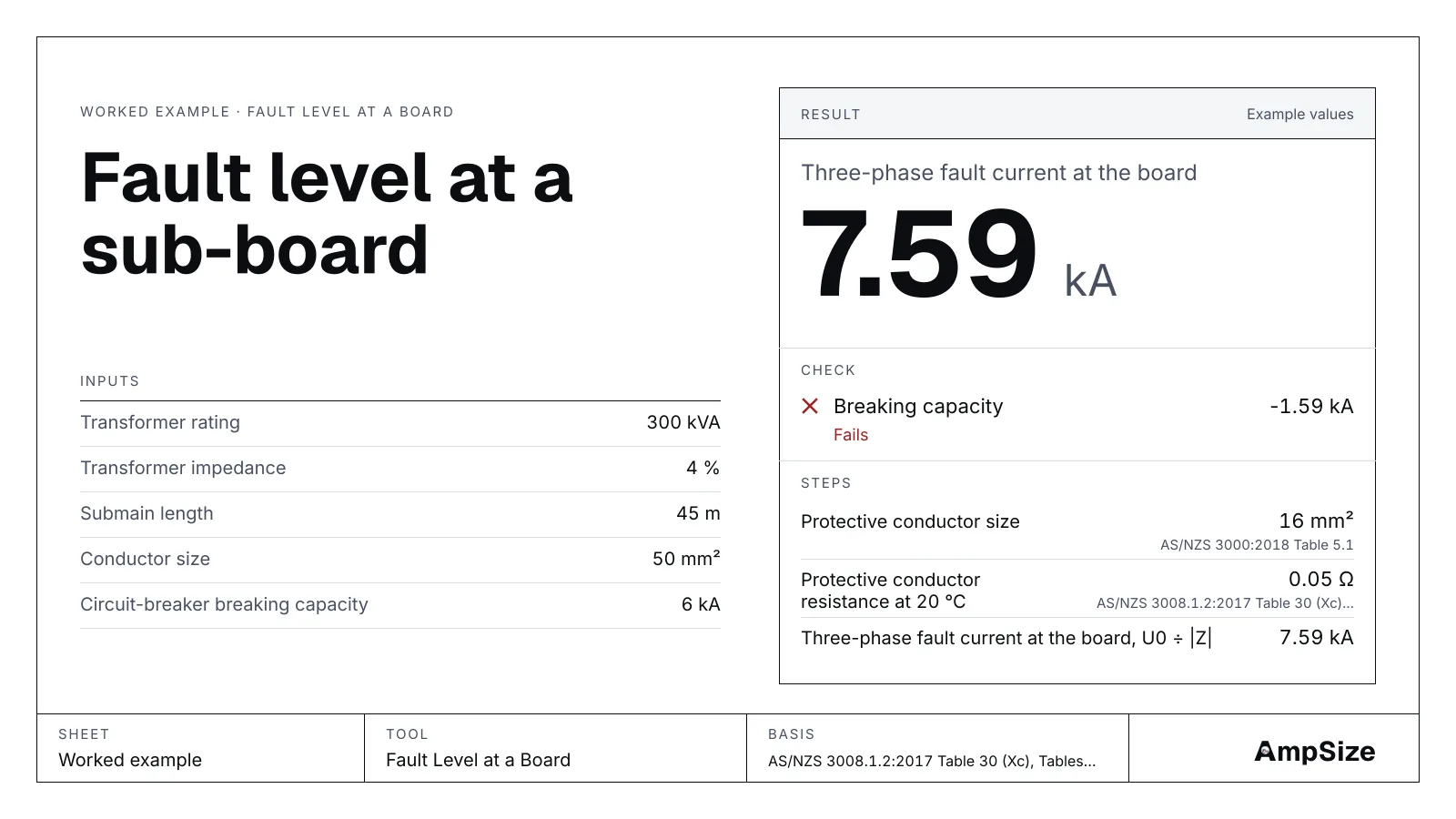
Every circuit-breaker has a breaking capacity, in kA. The fault current at its terminals has to stay below it. This guide works the fault level at one sub-board with the fault level tool, then checks two breaker ranges against it. The method is explained in Prospective fault current at a board.
The tool is an estimate by the impedance method. The network operator's figure, or a measurement, rules where you have one.
The site
- A 300 kVA, 400 V transformer with 4 % impedance, on the site.
- A sub-board 45 m away, fed by a 50 mm² copper PVC multicore submain in New Zealand.
- The protective conductor is 16 mm², from Table 5.1.
- The board is planned with 6 kA miniature circuit-breakers.
Step 1. The transformer
The transformer impedance per phase is U² ÷ S × Z%:
400² ÷ 300 000 × 0.04 = 0.02133 Ω
The phase voltage is 400 ÷ √3 = 230.9 V. At the transformer terminals the fault current is 230.9 ÷ 0.02133 = 10.83 kA. The tool takes the network above the transformer as infinite, and the transformer impedance as all reactance. Both choices give the highest current for these figures.
Step 2. The submain
The impedance tables give the 50 mm² resistance at 75 °C and its reactance. A cold cable passes the most current, so the tool scales the resistance down to 20 °C for the maximum.
| Figure | Value |
|---|---|
| Phase resistance at 75 °C, 45 m | 0.0212 Ω |
| Phase resistance at 20 °C, 45 m | 0.01743 Ω |
| Phase reactance, 45 m | 0.00359 Ω |
| Protective conductor at 20 °C, 16 mm² | 0.0518 Ω |
Step 3. The three-phase fault current
The resistance and the reactance add at right angles:
|Z| = √(0.01743² + (0.02133 + 0.00359)²) = 0.0304 Ω
230.9 ÷ 0.0304 = 7.59 kA at the board. The submain cut the fault current from 10.83 kA to 7.59 kA.
Step 4. The phase-earth fault current
The loop runs out on the phase conductor and back on the protective conductor. At a Dyn transformer, the tool takes the source loop as the phase impedance. The maximum, with the cable cold, is 3.14 kA. With the cable at 75 °C it is 2.63 kA. The lower figure is the one for disconnection time: take it to the loop impedance tool.
Step 5. Check the breakers
| Breakers | Breaking capacity | Fault level | Result |
|---|---|---|---|
| Planned | 6 kA | 7.59 kA | Fails |
| Next range up | 10 kA | 7.59 kA | Passes, 2.41 kA margin |
The 6 kA breakers are too small for this board. A 10 kA range passes. A longer submain lowers the fault level too: at 90 m the board sees 5.13 kA. Choose the breaker range for the board as built, not the cable you hope to run.
Step 6. Carry the figure on
The result carries a button, Check a cable's fault rating. It opens the fault rating tool with 7.59 kA filled in, for the cables that leave the board.
The result
| Board | Three-phase | Phase-earth, cold | Phase-earth, hot |
|---|---|---|---|
| At the transformer | 10.83 kA | 10.83 kA | 10.83 kA |
| 45 m of 50 mm² | 7.59 kA | 3.14 kA | 2.63 kA |
| 90 m of 50 mm² | 5.13 kA | 1.63 kA | 1.35 kA |
See also: Short-circuit withstand and the k factor and Industrial switchboards.