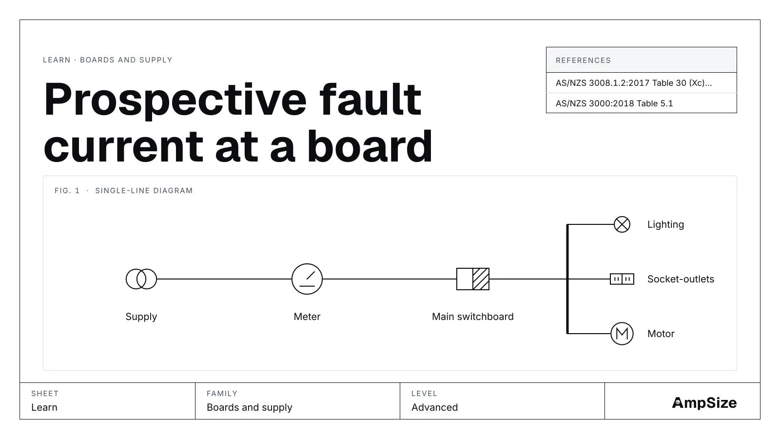
The prospective fault current is the current that flows if the phases short together, or a phase shorts to earth, at a point. It is set by the impedance between the source and that point. The lower the impedance, the higher the current.
Two numbers, two jobs
The highest fault current decides what the equipment has to survive. A circuit-breaker has to break it, and a cable has to carry it until the breaker clears. The lowest fault current decides whether the breaker trips fast enough. So a board has two figures, worked two ways.
| Figure | Worked with | Used for |
|---|---|---|
| Maximum | Cold cable, highest source | Breaking capacity, cable withstand |
| Minimum | Hot cable, the phase-earth loop | Disconnection time |
The source
A transformer's impedance per phase is U² ÷ S × Z%, from its line voltage, its rating and its nameplate impedance. A 500 kVA, 4.5 % transformer at 400 V gives 0.0144 Ω, or 16.04 kA at its terminals.
Where the supply comes from the network, the operator can give the fault level at the point of supply. The impedance is then the phase voltage over that current.
The fault level tool takes the source as all reactance, and the network above a transformer as infinite. Both give the highest current for the figures entered.
The submain
The cable adds resistance and reactance. The AS/NZS 3008.1 impedance tables give both, per kilometre. The resistance is printed at the conductor's operating temperature: 75 °C for PVC, 90 °C for XLPE. A fault at the start of the day finds the cable cold, with a lower resistance. So for the maximum, the tool scales the resistance to 20 °C by the conductor's temperature coefficient.
Resistance and reactance add at right angles. The three-phase fault current is the phase voltage over the size of the total impedance per phase.
The phase-earth loop
A fault from phase to earth sends current out on the phase conductor and back on the protective conductor. The loop is longer than the phase path, and the protective conductor is often smaller. So the phase-earth fault current is lower than the three-phase one at the same board.
At a Dyn distribution transformer the tool takes the source part of the loop as the phase impedance. On a network supply it reads Ze, the loop impedance at the origin.
What the tool does not do
- It applies no IEC 60909 voltage factor. That standard is not on hand.
- It does not add motor contribution, which raises the first cycles of a fault near large motors.
- It works one submain. For a chain of boards, take each board's result as the next source.
Then what
Compare the maximum with the breaking capacity of every device at the board. Carry it to the fault rating tool for the cables that leave the board. Take the minimum to the loop impedance tool for disconnection times.
Worked example
Fault level at a sub-board, 300 kVA transformer works one board: 7.59 kA three-phase, 6 kA breakers too small, 10 kA breakers with 2.41 kA margin.