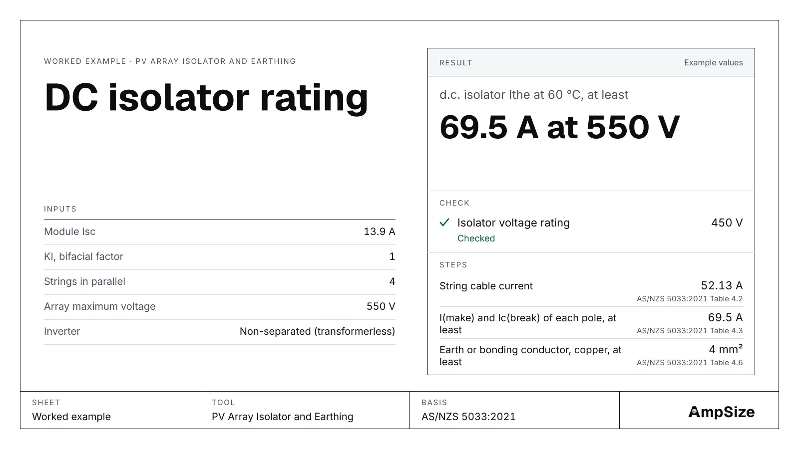
A domestic array has one d.c. isolator between the roof and the inverter. It must carry the array current, open under load and survive a fault. This guide rates that isolator with the PV isolator and earthing calculator. It also sizes the frame earth. The ideas are in PV array isolators and earthing.
The array
- Four strings in parallel, each of modules with an Isc of 13.9 A. That is about a 10 kW array.
- The string maximum voltage at the coldest cell is 550 V. The PV string tool gives it. See solar string sizing for a 600 V inverter.
- A transformerless inverter, which is non‑separated. The array has no functional earth.
- No string fuses. The isolator sits on the array cable, in the sun on the roof edge.
- The inverter a.c. cable is 6 mm².
Step 1. Find the circuit currents
The maximum string current is 1.25 × 1 × 13.9 = 17.38 A. The other three strings can push 3 × 17.38 = 52.13 A back into one string. AS/NZS 5033:2021 Table 4.2 sets the string cable at 52.13 A and the array cable at 69.5 A.
Open the tool with this array.
Step 2. Set the isolator minimums
- Voltage: at least 550 V (Cl 4.3.4.1).
- Ithe: at least 69.5 A. The isolator is outdoors in the sun, so read Ithe at 60 °C (Cl 4.3.4.2.3).
- Ie, the poles in series: at least 69.5 A.
- Make and break: the inverter is non‑separated, so each pole must make and break 69.5 A (Table 4.3).
Ithe at 60 °C is lower than the 40 °C figure on most data sheets. Use the de-rating curve, not the headline number.
Step 3. Check a data sheet that passes
A switch-disconnector lists 1000 V, an Ithe of 80 A at 60 °C, an Ie of 70 A and a make and break of 80 A per pole.
Open the tool with these ratings. All four checks pass. The margins are 450 V, 10.5 A, 0.5 A and 10.5 A. The Ie margin is thin, so a slightly lower Ie would fail.
Step 4. Check a data sheet that fails per pole
A second switch lists the same voltage, Ithe and Ie. Its make and break is 40 A. On a transformerless inverter, the tool needs that figure per pole. It must reach 69.5 A, so the check fails by 29.5 A.
Open the tool with the failing switch. Pick a switch with a higher per-pole rating. Do not accept a figure that is lower than the array current.
Step 5. Size the frame earth
The array is above 35 V and the inverter is non‑separated with no fuses. Table 4.6 column (b)(i) takes the AS/NZS 3000 earth for the inverter a.c. active. A 6 mm² a.c. cable gives 2.5 mm² from Table 5.1. The least frame earth is 4 mm², so the earth is 4 mm². Keep the path to the installation earth at 0.5 Ω or less.
The tool also tells you to fit a pressure-equalisation valve to the outdoor enclosure, and an earth fault alarm, because the inverter is non‑separated.
The result
| Item | Value |
|---|---|
| String cable current | 52.13 A |
| Array cable current | 69.5 A |
| Isolator Ithe at 60 °C, at least | 69.5 A at 550 V |
| Isolator Ie, at least | 69.5 A |
| Make and break per pole, at least | 69.5 A |
| Earth conductor, at least | 4 mm² |
The tool does not size the cables. Size each one with the DC cable size tool at the current above.