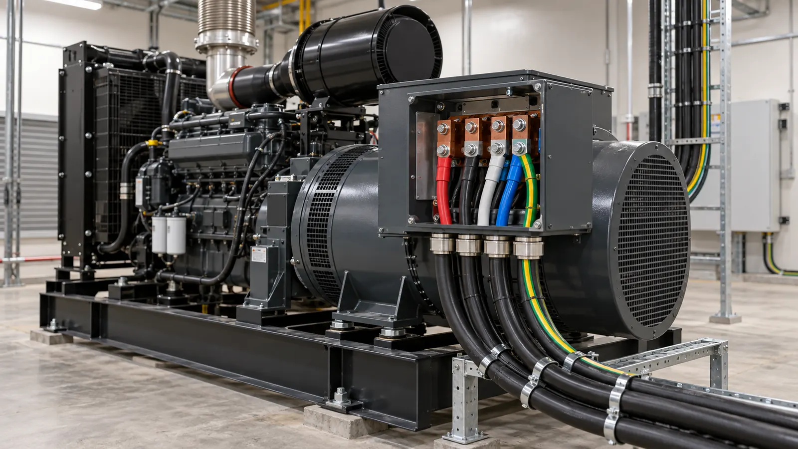
A winter backup design needs two currents from the generator, not one. The full load current sizes the cable and the changeover switch. The fault current sets what the downstream protection can see while the set carries the load.
The inputs
The standby set is 500 kVA, three phase, 400 V, at 0.8 power factor. The nameplate subtransient reactance is 12 %.
The subtransient reactance is the value the alternator data sheet calls X''d. It is a percentage of the machine base impedance. It is also the only input that decides the fault figure. A set of the same kVA with a higher reactance gives a lower fault current.
The clause
Cl 7.3 of AS/NZS 3000:2018 covers generating sets as an alternative supply. Cl 2.5.4.1 of AS/NZS 3000:2018 is the fault current rule for the protective device and the conductors it protects.
The steps
The engine works the full load current from the kVA, the line voltage and root three. It then divides that current by the per unit subtransient reactance.
- Full load current: 721.69 A
- Real power: 400 kW
- Fault current: 6014.07 A
The result
The set delivers 721.69 A at its rating. It delivers 6014.07 A into a bolted three phase fault at its terminals. The 12 % reactance alone fixes the ratio between the two.
That fault figure is the initial symmetrical value. The engine states the limit on every run. The number ignores the decay from the subtransient value to the transient and synchronous values. It also ignores any excitation limit. A few cycles into the fault the current is much lower. Some sets settle near their rated current unless the regulator holds a higher value.
This is the point that changes a design. A grid supply holds its fault current for as long as the fault lasts. The source impedance is small and the source is large. A generator cannot do that. The current it supplies falls away while the protection is still deciding.
An inverse time relay graded on the grid fault level sits far out on its curve. It can also fail to pick up while the set runs. Some sets carry a field forcing feature to hold the fault current for a few seconds. The data sheet states whether this one does. A device that clears in 0.1 s on the grid can take much longer on the generator. Check the disconnection times on both supplies.
The earth fault path needs its own check. The generator neutral earthing arrangement differs from the network one. Run that check on the generator source, not on the grid source.
Take 721.69 A into the cable size tool. Use it for the run from the alternator to the changeover switch, with the real route length.
Take 6014.07 A into the fault rating tool. Pair it with the clearing time of the device that protects that cable. Then run the protection settings twice, once at each fault level.
This page is a design aid. Verify every value against the current edition of the standard.
See also: Generator full load current: 200 kVA to amps, Generator sizing for a 150 kVA holiday park and Short-circuit withstand and the k factor.