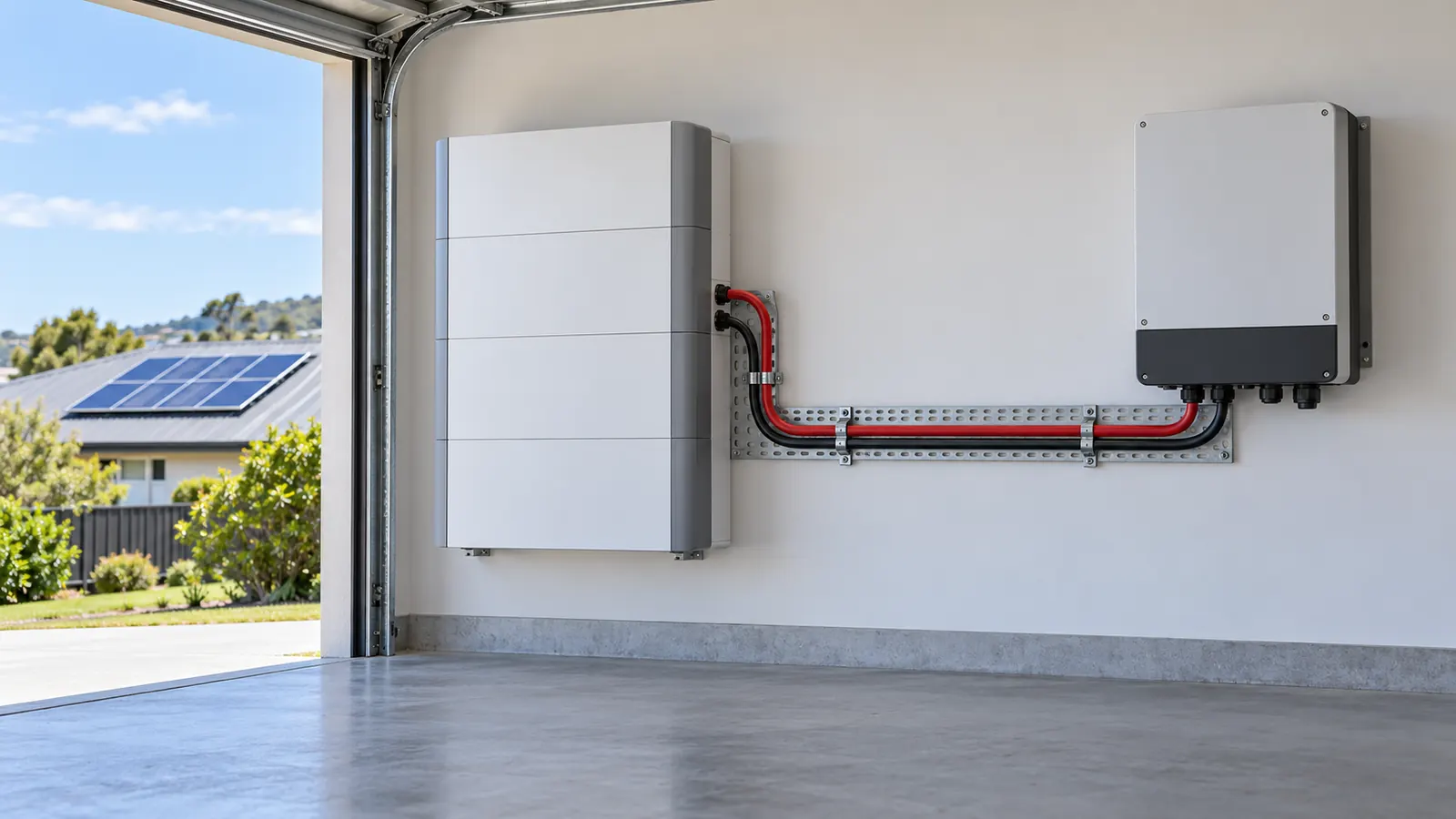
AS/NZS 3008.1.1:2025 gives d.c. current ratings and d.c. voltage drop for circuits up to 1500 V d.c. This guide sizes two d.c. circuits with the DC cable size calculator. The first is a 48 V battery run. The second is a 600 V PV array feed.
How the calculator sizes a d.c. cable
The calculator tests each standard size in turn. A size passes two checks.
- Current. The corrected rating Iz must be at or above the design current. Iz is the d.c. rating multiplied by the correction factor (derating factor in 2017).
- Voltage drop. The drop must be inside the limit for the supply type.
The d.c. ratings come from Tables 3.21 and 3.22 for two single-core cables. Tables 3.24 and 3.25 give them for one 2-core cable. The d.c. mV/A.m comes from Tables 4.16, 4.18, 4.21 and 4.23.
The voltage drop limit depends on the supply
Cl 4.1.1 sets the limit by the type of supply. The calculator offers four supply types.
| Supply type | Limit |
|---|---|
| ELV, 120 V d.c. or less | 10 % |
| LV, connected to a network | 5 % |
| LV, from a dedicated substation | 7 % |
| LV, stand-alone system | 11 % |
The limit is a percentage of the nominal voltage. At 48 V, 10 % is 4.8 V. At 600 V, 5 % is 30 V. The calculator picks the supply type from the voltage. You can change it, and the limit follows it until you type a limit of your own.
Why the d.c. mV/A.m covers both conductors
Current flows out on one conductor and back on the other. Cl 4.7 gives the drop from the mV/A.m, and the d.c. mV/A.m counts both conductors. So you multiply it by the route length one way. Do not double the length.
A d.c. circuit has no reactance and no power factor. The drop comes from the conductor resistance alone. That is why the d.c. mV/A.m is twice the Ω/km resistance of one conductor.
Circuit 1: a 48 V battery to an inverter
The inputs:
- Supply: 48 V d.c., ELV, so the limit is 10 %
- Design current: 105 A, the most the inverter draws from the bank
- Route length: 4 m
- Cables: two single-core copper cables with PVC insulation
- Installation: unenclosed and touching, in air at 40 °C, with no other circuit near
The air is at the 40 °C reference, and no other circuit shares the route. So the correction factor is 1.
Table 3.21 rates 25 mm² at 97 A for this method. That is less than 105 A, so 25 mm² fails. The next size, 35 mm², carries 119 A and passes.
The mV/A.m of 35 mm² is 1.27. The drop is 1.27 × 105 A × 4 m ÷ 1000 = 0.53 V. That is 1.11 % of 48 V, well inside the 4.8 V limit.
The calculator selects 35 mm², with Iz of 119 A. The current sets the size. Open circuit 1 in the calculator.
On a short battery run, the current usually sets the size. A long run at 48 V can let the drop take over.
Circuit 2: a 600 V PV array feed
The inputs:
- Supply: 600 V d.c. The inverter connects to the network, so this guide uses the 5 % limit.
- Design current: 20 A
- Route length: 50 m
- Cable: one 2-core copper cable with XLPE insulation
- Installation: enclosed in air at 40 °C, with no other circuit near
Table 3.25 rates 1.5 mm² at 20 A for this method, so 1.5 mm² carries the current. Its mV/A.m is 34.7. The drop is 34.7 × 20 A × 50 m ÷ 1000 = 34.7 V. That is 5.78 % of 600 V, above the 5 % limit, so 1.5 mm² fails.
2.5 mm² carries 28 A. Its mV/A.m is 18.9, so the drop is 18.9 V. That is 3.15 %, inside the limit.
The calculator selects 2.5 mm². The voltage drop sets the size. Open circuit 2 in the calculator.
Check which supply type fits your installation. A stand-alone system takes a different limit.
New Zealand: a derived result
AS/NZS 3008.1.2:2017 has no d.c. ratings. For New Zealand, the calculator uses the AS/NZS 3008.1.1:2025 d.c. ratings. It corrects them from 40 °C to the air temperature you enter, 30 °C by default. A buried run corrects from 25 °C to the soil temperature, 15 °C by default. No NZ table prints these figures, so the result says Derived.
Run circuit 1 in New Zealand at 30 °C. The correction factor is 1.13. So 25 mm² carries 97 A × 1.13 = 109.61 A, which is more than 105 A. The calculator selects 25 mm² with a drop of 0.74 V, 1.55 %. Open the NZ case.
What the calculator does not check
- The d.c. protective device. Check its rating against Iz.
- The battery fault current. A battery can deliver a large fault current. Check the cable and the device against the battery maker's figure.
To size the bank itself, use the battery calculator. The standards page lists the d.c. tables and clauses that the DC calculator reads. The glossary defines d.c. and the other terms on this page.
This page is a design aid. Verify every value against the current edition of the standard.