An arc flash study turns a fault current and a clearing time into an energy at a distance. The method behind that conversion is empirical, and its range of validity is part of the method.
The question
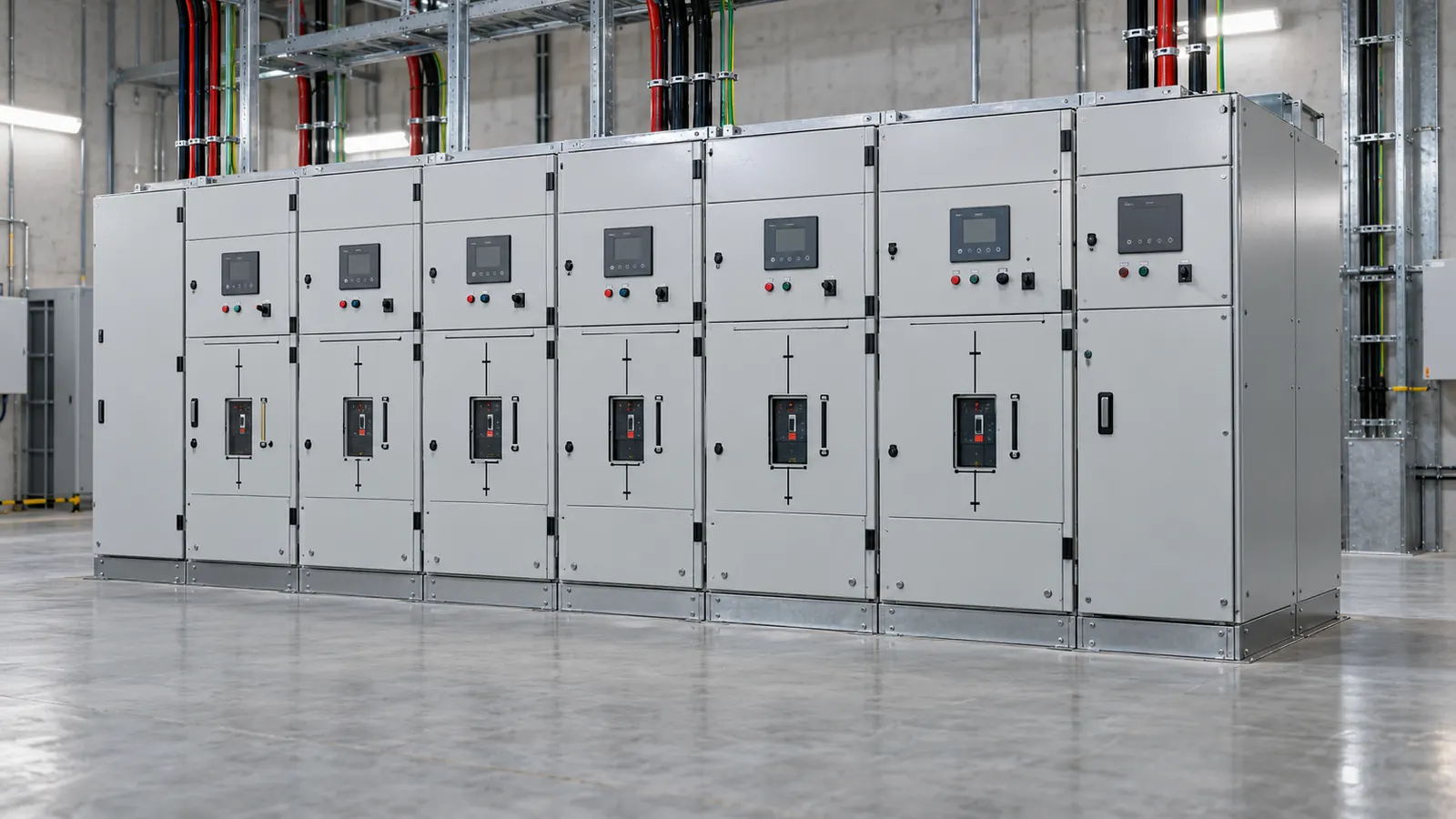
A 400 V switchboard sees 25 kA of bolted fault current. The upstream device clears in 0.2 s. How much incident energy reaches a worker standing at the usual distance?
The inputs
- System voltage: 0.4 kV
- Bolted fault current: 25 kA
- Clearing time: 0.2 s
- Equipment: switchgear, enclosed, earthed
- Working distance: 455 mm
- Electrode gap: taken from the equipment type
The clause and the model
Cl 4 of IEEE 1584-2002 sets out the empirical model. Laboratory tests produced the coefficients, which is why the model carries stated bounds on voltage, fault current and electrode gap. Outside those bounds the coefficients no longer describe what the tests measured.
Cl 5.2 gives the arcing current. An arc has resistance, so the current through an arc sits below the bolted fault current. The protective device sees that lower current. A lower current often falls on a slower part of the device curve.
Cl 5.3 gives the normalised incident energy at a reference distance and time. Cl 5.4 scales that energy to the real clearing time and the real working distance. Cl 5.5 gives the arc flash boundary. The boundary marks the distance at which the energy reaches the onset of a second degree burn.
Above 15 kV the empirical model does not apply. The tool switches to the Lee model there and states the switch in a note. The 2018 edition of IEEE 1584 uses a different model again, and that edition is not in the tool.
The steps
The tool takes the equipment type first and reads an electrode gap of 32 mm for switchgear.
It then applies Cl 5.2 and gets an arcing current of 11.49 kA. That sits well under the 25 kA bolted figure. A clearing time therefore has to come from the arcing current, not from the bolted current.
Cl 5.3 gives a normalised incident energy of 3.262. Two factors then scale it. The calculation factor for this equipment and voltage is 1.5. The distance exponent is 1.473.
Applied at 0.2 s and 455 mm, the result is 7.54 cal/cm².
Cl 5.5 gives an arc flash boundary of 1,588.31 mm. The tool places 7.54 cal/cm² in PPE category 2.
The result
The study passes through the model cleanly at 400 V. The numbers that move it most are the clearing time and the working distance. Halving the clearing time roughly halves the energy. The distance exponent of 1.473 means that energy falls faster than distance rises.
The model says nothing about what happens outside its tested range. Check the voltage, the fault current and the gap against the bounds in Cl 4 before trusting a result. Treat a figure near an edge as an indication only. Commission a study against the current edition before relying on it.
This page is a design aid. Verify every value against the current edition of the standard.
See also: Arc flash incident energy at a 400 V switchboard, Arc flash boundary at a motor control centre and Arc flash basics.