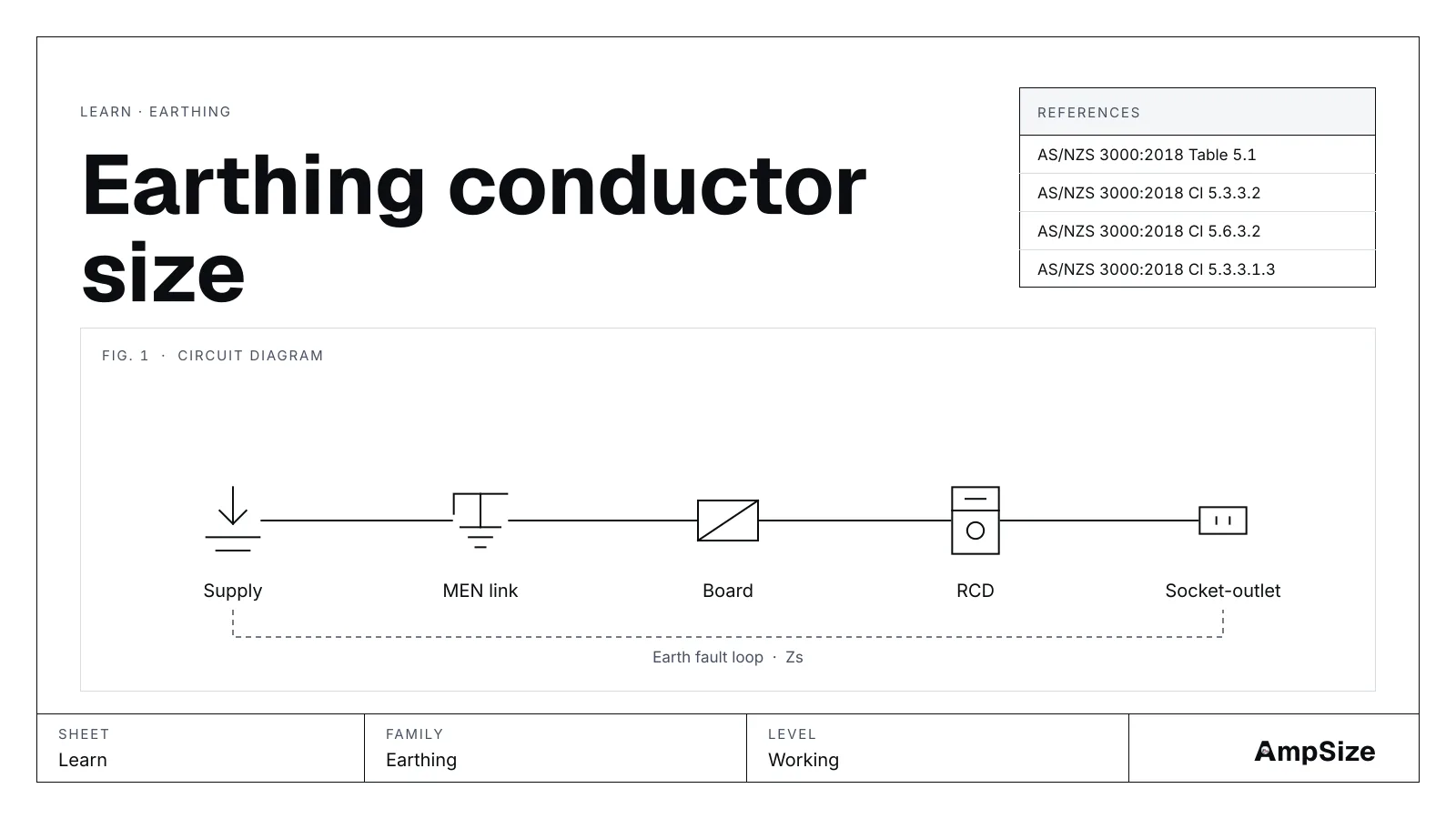
An installation has three kinds of earth conductor. Each one has its own size rule. Many mistakes come from using one rule for all three. This page separates them.
The three conductors
The protective earthing conductor runs with the active conductors in a cable. It carries fault current back to the source.
The main earthing conductor joins the main earth bar to the earth electrode. It sits at the origin of the installation.
The bonding conductor joins exposed metalwork, such as a water pipe, to the main earth bar.
Each has a different job. The tool reports a size for all three.
Size from the table
Table 5.1 of AS/NZS 3000:2018 gives the protective earthing conductor size from the size of the active conductor. A larger active conductor needs a larger earth.
Cl 5.3.3.2 sets the main earthing conductor. Cl 5.6.3.2 sets the bonding conductor. The tool reads these from the largest active size you enter and the material.
A worked case from the table
Take copper actives. The largest active is 25 mm².
- Protective earthing conductor from the table: 6 mm²
- Main earthing conductor: 6 mm²
- Bonding conductor: 4 mm²
The tool selects 6 mm² as the protective earthing conductor. The table size is enough here.
Open the earthing tool with these inputs.
Size by calculation
The table assumes a normal fault. A large fault current with a slow device can ask for more. Cl 5.3.3.1.3 gives the check by calculation. It uses the fault current, the disconnection time and a k value for the conductor.
The area is S = I × √t / k. I is the fault current in amps. t is the time in seconds. k depends on the material and insulation.
Take the same 25 mm² active. The fault current is 3000 A. The device opens in 0.4 s. The conductor is PVC-insulated copper, not laid up with other conductors.
- k value used by the tool: 136
- Calculated area: 3000 × √0.4 / 136 = 13.951 mm²
- Rounded up to a standard size: 16 mm²
The calculated size is larger than the table size of 6 mm². The tool warns you to use the calculated size. The protective earthing conductor becomes 16 mm².
The main earthing conductor and the bonding conductor stay at 6 mm² and 4 mm². Those two do not take the adiabatic check in the tool.
Open the earthing tool with the calculation on.
Why the time matters
The area grows with the square root of the time. A slow device lets the fault energy build. A device that opens in 0.1 s needs a smaller earth than one that opens in 0.4 s. The same fault current is then less severe.
The fault current figure comes from the supply. The fault rating tool and the loop impedance tool help you find it.
Where it goes wrong
One size is used for all three. The three conductors follow different rules. Check each one.
The table is trusted without a fault check. A high fault current with a slow device can ask for a larger earth.
The k value is copied from another case. A bare conductor and a PVC conductor have different k values. Select the one that matches the cable.
The earth is sized from the load, not the active. The rule follows the active conductor size.
Aluminium is entered as copper. The tool has a material select. Set it first.
This page is a design aid. Verify every value against the current edition of the standard.
See also: The MEN system explained, Short-circuit withstand and the k factor and Consumer mains fault withstand on 16 mm².