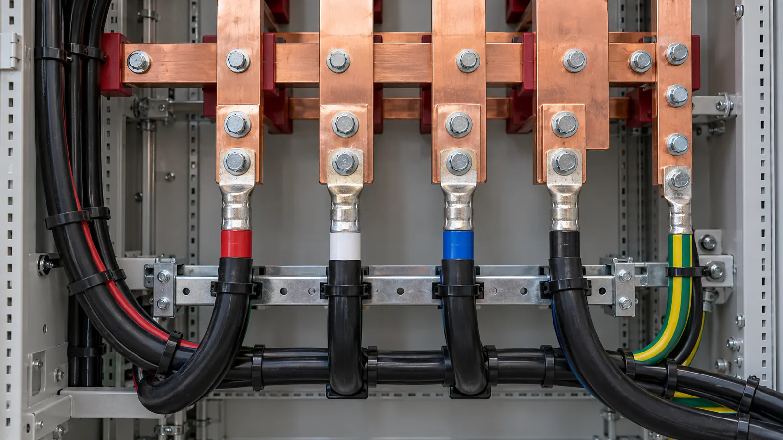
Current-carrying capacity is about hours. Short-circuit withstand is about the first few cycles. A cable that carries its load all day can still be destroyed by a fault that lasts a tenth of a second, and that is a separate calculation.
Why the first cycles are different
A short circuit draws far more current than the cable was sized for. The conductor heats almost instantly, and the heat has nowhere to go in the time available. None of it reaches the insulation surface, the air or the soil.
The check treats that as adiabatic: all the energy stays in the conductor and raises its temperature. The question is whether the conductor reaches a temperature that damages the insulation before the protective device opens.
That is why the check is about energy, not current. A large current for a very short time and a smaller current for a longer time can do the same damage.
The three inputs
Prospective fault current. The current that flows at the point of the fault, set by the source impedance and everything between the source and the fault. A transformer secondary gives the highest figure in most installations. Cl 2.5.4.1 of AS/NZS 3000:2018 requires equipment and conductors to withstand it.
Clearing time. How long the device takes to open, from the fault appearing to the current reaching zero. This is the input people get wrong, and it is the one with the most leverage.
k factor. A number for the conductor material and the insulation, taken from Table 52 and Table 53 of AS/NZS 3008.1.2:2017. Copper carries a higher k than aluminium. XLPE carries a higher k than PVC, because it tolerates a higher final temperature.
The three combine in the adiabatic equation of Cl 5.3, which relates the let-through energy to the square of the conductor size and the square of k. Cl 5.3.3.1.3 of AS/NZS 3000:2018 applies the same reasoning to protective earth conductors.
A worked check
Take a prospective fault current of 10 kA cleared in 0.1 s. The cable is 25 mm² copper with XLPE insulation.
The tool reads a k factor of 143 from Table 52. From the fault current and the clearing time it returns a minimum conductor size of 22.11 mm². The 25 mm² conductor installed is above that, so the check passes.
The tool states the margin the other way as well. A 25 mm² copper XLPE conductor withstands 11.31 kA for 0.1 s. The 10 kA prospective current sits below that.
Open the cable fault rating calculator with these inputs.
What moves the required size
The let-through energy rises with the square of the current and with the time. The required conductor size follows the current directly and follows the square root of the clearing time. Current has the stronger effect, and time is usually the input a designer can change.
This is why protection settings and conductor sizes are one problem, not two. A cable that fails the withstand check has two fixes. Install a larger conductor, or clear the fault faster with a current-limiting device or a lower time setting.
Grading pushes the other way. An upstream device is deliberately slower than the one below it, so it can let a downstream fault clear first. Every step up the chain adds time, and the conductors at the top of the chain carry both the highest fault current and the longest clearing time.
Where the check bites
The consumer mains and the main switchboard connections see the highest fault current in an installation, because they sit closest to the transformer. A short run of small conductor between a main switch and a meter is a common place for the check to fail.
Protective earth conductors carry the full fault current for the full clearing time, and they are usually smaller than the actives beside them. Sizing them from a table without the withstand check is the other common gap.
Parallel conductors share the fault current, but only if they are the same size, the same length and terminated the same way. The tool checks one conductor.
What the check does not cover
The adiabatic equation covers thermal damage to the conductor and the insulation. It does not cover the mechanical forces between conductors during a fault, which is a busbar and a switchboard question. It does not cover the device itself, which needs its own breaking capacity at the same fault level.
It also assumes the current is there for the whole clearing time. A current-limiting device cuts the peak before the natural zero, so the real let-through energy is lower than the calculation. The device manufacturer publishes that data.
Three habits worth keeping
Take the clearing time from the device curve. A nominal figure from memory can be out by an order of magnitude, and the result moves with it.
Check the earth conductor, not just the active. It is smaller and it sees the same fault.
Re-run the check when the supply changes. A larger transformer or a new network connection raises the fault current everywhere downstream.
This page is a design aid. Verify every value against the current edition of the standard.