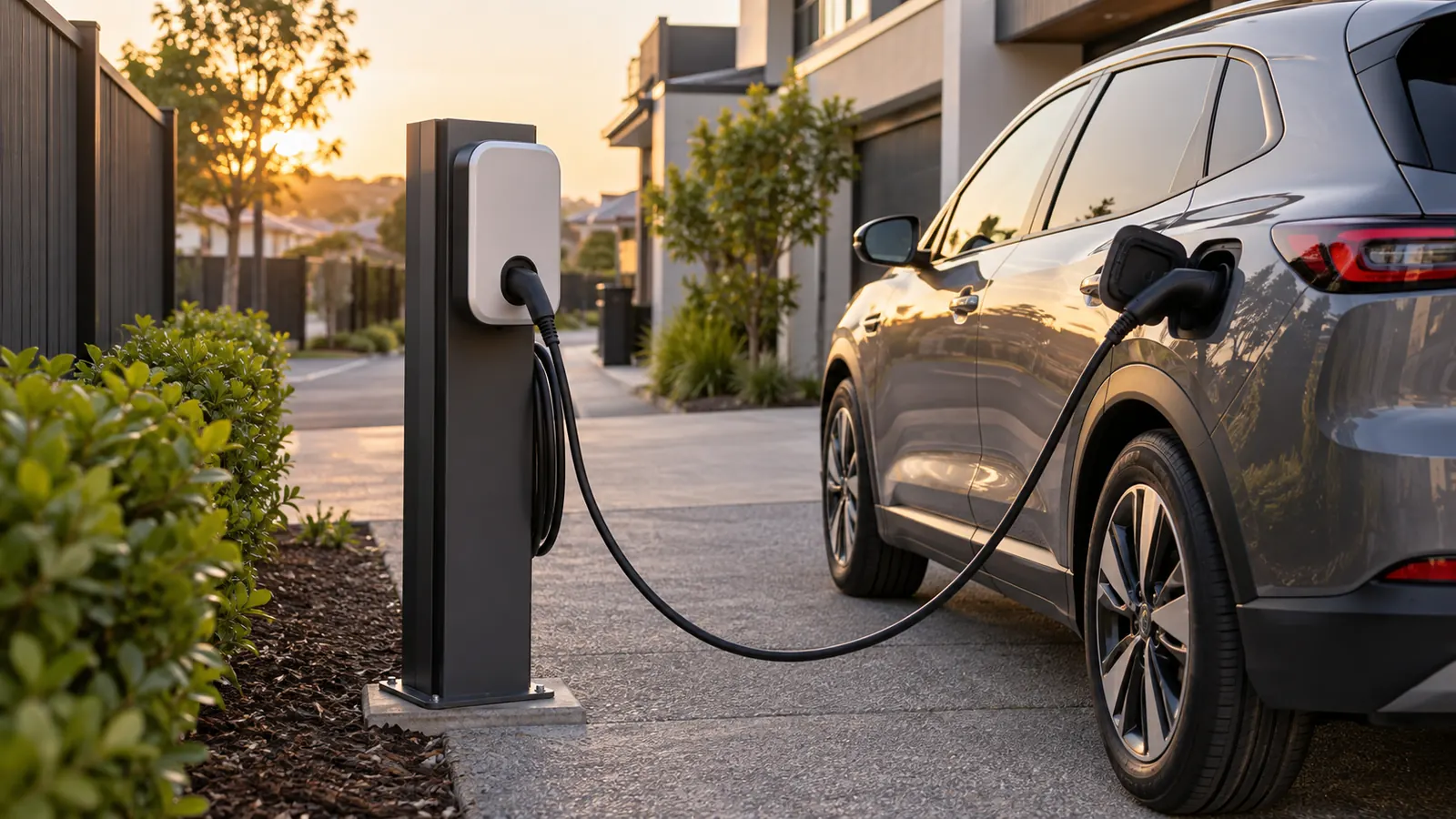
An EV charger is a long duration load on a domestic switchboard. Clause 7.9 of AS/NZS 3000:2018 is the part of the standard written for it.
The question
A 32 A charger goes on a garage wall, 25 m of cable from the switchboard. What conductor size carries it, and which clauses set the surrounding requirements?
The inputs
- 230 V, single phase, 32 A design current
- Power factor 1.0
- Run length 25 m
- Installation method: partly in insulation
- Wiring enclosure: none
- Ambient temperature 35 °C, one circuit on the route
- Copper, PVC, multicore, one cable
- Voltage drop limit 5 %
- Device: curve C, 32 A, with an external loop impedance of 0.35 Ω
The clauses
Cl 7.9.2 covers the supply arrangement for electric vehicle charging equipment. A charger draws close to its rated current for hours. The clause therefore treats a charger as its own circuit, not as an addition to a socket‑outlet circuit.
Cl 7.9.3 covers residual current protection for the charging circuit. Charger electronics can pass d.c. residual current, and the RCD type has to suit what the equipment produces. The cable size tool does not choose an RCD product for this circuit. The RCD selection tool reports the requirement and the trip limits. It also reports the type where the clause names one.
Cl 7.9.4 covers a charging circuit outside a domestic installation. It sets that circuit's own Type B device. Cl 7.9.3.3(e) sets the isolating switch instead.
Demand is a separate question. Table C1 of AS/NZS 3000:2018 places electric vehicle charging in group J(iv) for a domestic installation. Table C2 places it in group C(ii) for other installations. The maximum demand tool applies whichever group the chosen table gives.
Amendment 1 revised Clause 7.9. Check the amendment status of the copy in front of you before citing a subclause.
The steps
The cable size tool sizes against the derated capacity first.
At 35 °C the ambient factor is 0.94. One circuit gives a grouping factor of 1, so the total derating factor is 0.94.
Dividing 32 A by 0.94 gives a required tabulated current of 34.04 A. The tool then walks the standard sizes in AS/NZS 3008.1.2:2017 Table 13 and takes the first that passes every check.
6 mm² carries 31.96 A after derating, which falls under the 32 A design current. It fails on capacity.
10 mm² carries 44.18 A after derating. Voltage drop over 25 m comes to 1.55 %, inside the 5 % limit. The 32 A curve C device sits correctly against both the load and the cable. Loop impedance reaches 0.55 Ω, and the earth conductor for that active is 4 mm².
The result
The circuit needs 10 mm² copper. A 32 A number suggests 6 mm² on paper. That cable falls one size short here, because the insulation contact and the 35 °C ambient take the rating down.
Two inputs move this answer most. The installation method sets the base rating. A charger cable that leaves a wall cavity and crosses a ceiling changes method partway. The ambient temperature matters for the same reason, since a roof space in summer runs hotter than 35 °C.
The cable is one part of the design. Cl 7.9.3 still governs the residual current device, and Cl 7.9.3.3(e) still governs the isolating switch. This tool outputs neither.
This page is a design aid. Verify every value against the current edition of the standard.
See also: 22 kW EV charger amps at 400 V three‑phase, EV charger cable size for a 7 kW 32 A circuit and Current-carrying capacity and derating.