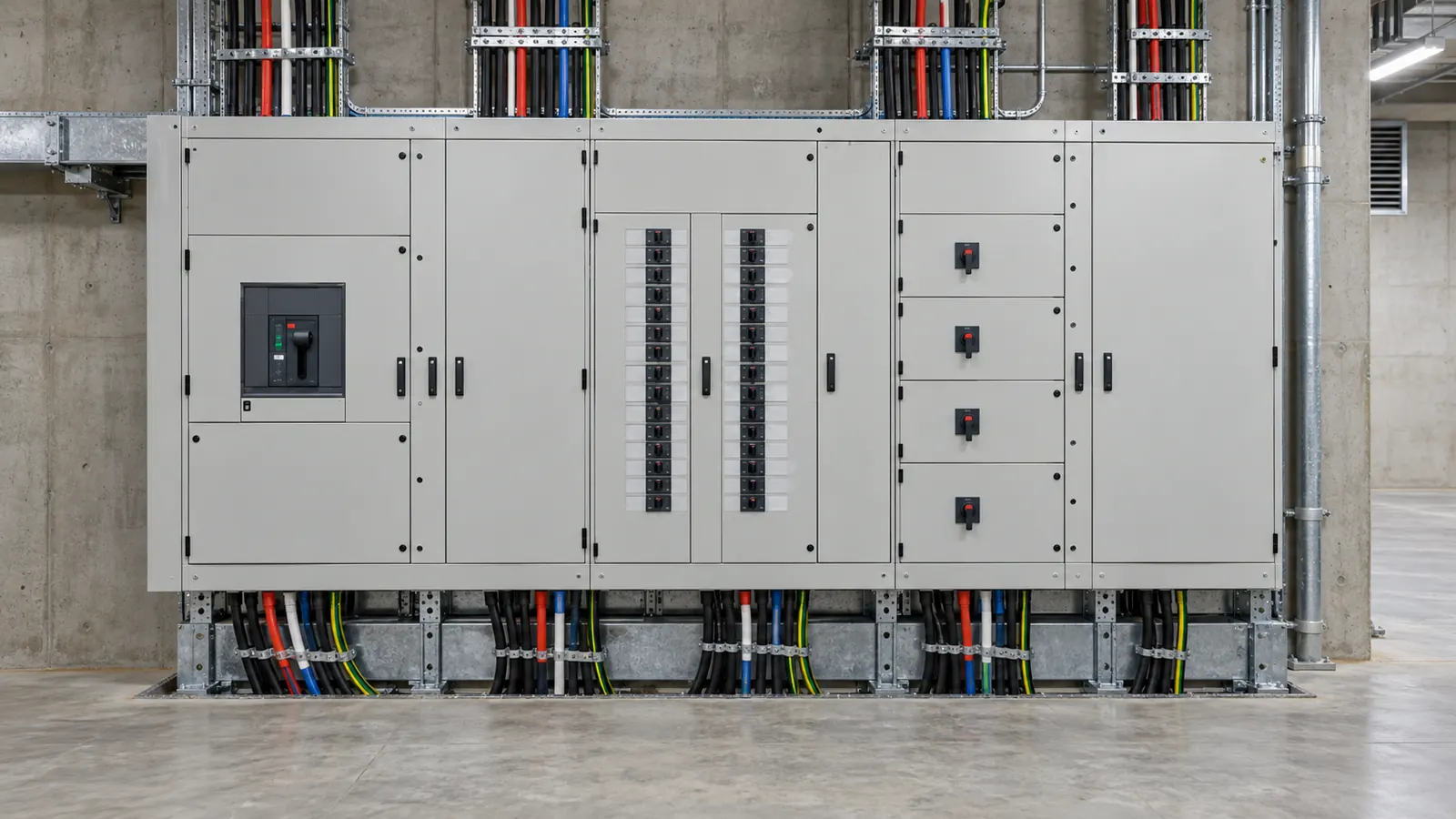
A switchboard has a fault level. The cable feeding it has to survive that fault for as long as the device takes to clear it. The current rating of the cable says nothing about that. The adiabatic check does.
The inputs
An incoming cable at a commercial main switchboard.
- Prospective fault current: 16 kA
- Clearing time: 0.1 s
- Installed conductor: 70 mm²
- Material: copper
- Insulation: XLPE
The fault current is a network figure. The distributor supplies it, or a transformer calculation gives it. The clearing time belongs to the device that clears the fault, which is the upstream one.
The clause and the table
Cl 5.3 of AS/NZS 3008.1.2:2017 gives the adiabatic equation, I²t = k²S². Cl 2.5.4.1 of AS/NZS 3000:2018 is the requirement that the conductor withstand the prospective fault current.
The k factor comes from Table 52 of AS/NZS 3008.1.2:2017. It depends on the conductor material and the insulation type. Copper with XLPE gives k = 143 in this case.
The method assumes that no heat leaves the conductor during the fault. That holds for short durations and is a conservative assumption for longer ones.
The steps
The tool rearranges the equation for the conductor area. It takes the fault current of 16 kA, the clearing time of 0.1 s and the k factor of 143.
That gives a minimum conductor size of 35.38 mm². This is a calculated area, not a standard size. The installed conductor has to be at least that large.
The tool then runs the equation the other way. It asks what fault current the installed 70 mm² conductor withstands for 0.1 s, and returns 31.65 kA.
The result
- Minimum conductor size: 35.38 mm²
- Installed size: 70 mm²
- Withstand fault current: 31.65 kA
- k factor: 143
The check passes. 70 mm² is above the 35.38 mm² minimum, and the 31.65 kA withstand is above the 16 kA fault level.
Keep the three figures apart. 35.38 mm² is what the fault demands. 70 mm² is what the design installed. Current rating rather than fault withstand usually drives that choice. 31.65 kA is the headroom that size happens to give at this clearing time.
Clearing time drives the answer
The energy in the equation is current squared multiplied by time. The required area follows the square root of the clearing time. It follows the fault current directly.
Run the same case at 0.2 s and the minimum size becomes 50.04 mm². The withstand of the installed 70 mm² conductor falls to 22.38 kA. The fault current did not change.
That makes the clearing time the input to check first. A main switch with a short time delay holds the fault far longer than an instant trip. An upstream relay set for grading does the same. Use the time the clearing device takes at 16 kA, read from its curve.
Insulation matters as well. Changing XLPE to PVC on the same copper conductor lowers the k factor. The minimum size rises with it for the same fault.
The switchboard has its own rating
This check covers the incoming conductor. The switchboard carries a separate short-circuit rating, and the cable result says nothing about it. A board rated below the 16 kA fault level fails even where the cable passes.
The device that clears the fault also has a breaking capacity. Check that figure against the same 16 kA. Three parts therefore have to hold at the fault level: the cable, the board and the device.
This page is a design aid. Verify every value against the current edition of the standard.
See also: AS/NZS 3000 Table 8.1: max Zs by curve and rating, Earth fault loop impedance and maximum Zs and Short-circuit withstand and the k factor.