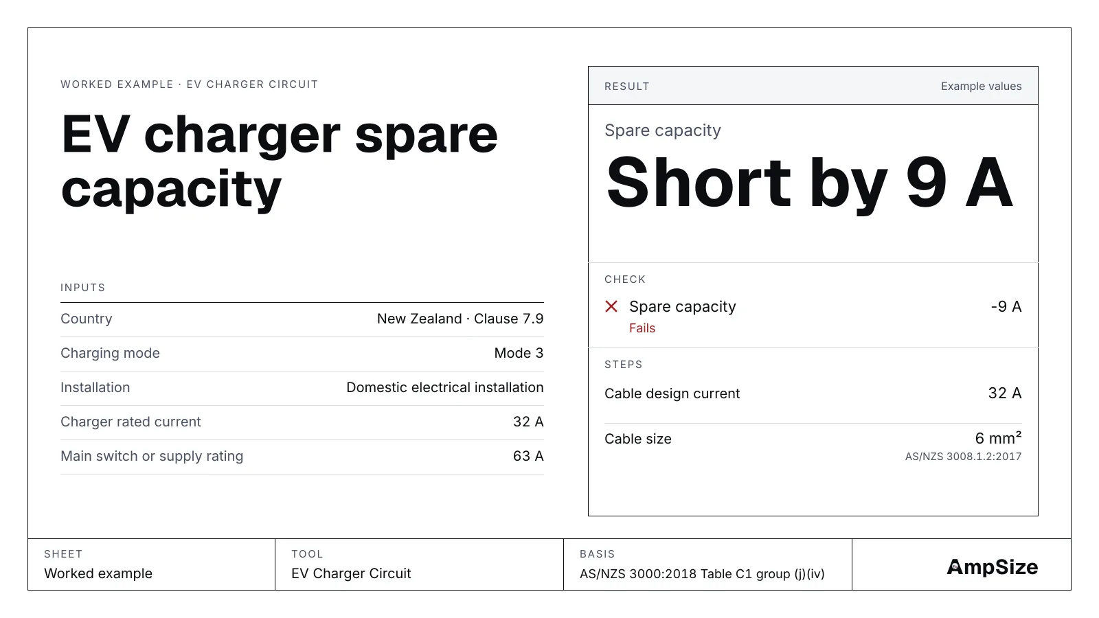
A 7 kW wall charger draws 32 A for hours at a time. Before you order one, check that the house board has room for it. This guide works one house with the EV charger tool: the spare capacity first, then the managed case, the cable and the RCD. The demand rules behind the check are in EV charging load and spare capacity.
The tool compares the figures you type. It does not measure the house, and it does not rule on the installation.
The house
- A single‑phase house in New Zealand with a 63 A main switch.
- The maximum demand without the charger is 40 A. It comes from the maximum demand tool, or from a logged reading.
- One 7 kW Mode 3 wall charger, 32 A, single‑phase.
- The charger sits in the garage, 15 m of cable from the board, enclosed in air.
Step 1. Find the spare capacity
The spare capacity is the main switch rating less the maximum demand: 63 − 40 = 23 A. A 32 A charger with no load management does not fit: the tool reads Short by 9 A.
From the maximum demand tool, the result carries a button, Check EV charger spare capacity. It opens the EV charger tool with the 40 A filled in. Enter the 63 A main switch beside it.
Step 2. Count the charger
In a New Zealand domestic installation, the tool reads Table C1 group (j)(iv): full connected load. The charger counts at its whole 32 A. In Australia, and outside a home, the tool reads Appendix P Paragraph P2. It counts every charging point at full rated current, all at once.
| Figure | Value |
|---|---|
| Spare capacity | 23 A |
| Charger demand | 32 A |
| Left after the charger | −9 A |
The charger is 9 A short. The tool marks the check as failed.
Step 3. Try load management
A load management device watches the main and turns the charger down when the house is busy. Turn on Load management device in the tool and enter its limit: 20 A.
The managed case now fits, with 3 A left. The unmanaged check stays on the result beside it. The managed case relies on the device and its setting, so keep both figures on the job record.
A NOTE to Clause 7.9.3.3(a) points to mains upgrades and load management above 20 A single‑phase. A NOTE is guidance, and the tool names it as one.
Step 4. Or choose a smaller charger, or a larger main
Two other fixes close the gap:
| Change | Charger demand | Spare | Left |
|---|---|---|---|
| 16 A charger setting | 16 A | 23 A | 7 A |
| 80 A main switch | 32 A | 40 A | 8 A |
A larger main switch is a network question as well. Ask the lines company what the connection can carry before you plan on it.
Step 5. Size the cable
The tool sizes the cable through the cable size engine. In a New Zealand home, Clause 7.9.3.3 prints a 32 A capacity for a single‑phase Mode 3 circuit. So the tool sizes at 32 A even when you set the charger to 16 A.
At 15 m, enclosed in air, PVC copper gives 6 mm², with 1.57 % voltage drop. To set the grouping or the ambient, open the cable size tool with the same run.
Step 6. Name the RCD
In New Zealand, Clause 7.9.3.3 sets a separate 30 mA Type B device in every live conductor. For Mode 3, its Exception names Type A with an RDC-DD instead.
In Australia, Paragraph P4.1 names a 30 mA device of at least Type A for each charging point. A Mode 3 outlet adds a d.c. measure: Type B, or Type A with 6 mA d.c. detection. Many wall chargers detect d.c. fault current themselves. Then Type A follows. Turn on The charger detects d.c. fault current in the tool, and check the maker's data.
The result
| Case | Spare capacity | Charger | Fits |
|---|---|---|---|
| 32 A charger, no management | 23 A | 32 A | No, 9 A short |
| 32 A charger, managed to 20 A | 23 A | 20 A | Yes, 3 A left |
| 16 A charger setting | 23 A | 16 A | Yes, 7 A left |
| 80 A main switch | 40 A | 32 A | Yes, 8 A left |
See also: EV charger 7 kW cable size at 32 A, AS/NZS 3000 Clause 7.9 EV charging in NZ and RCD types and where they are required.