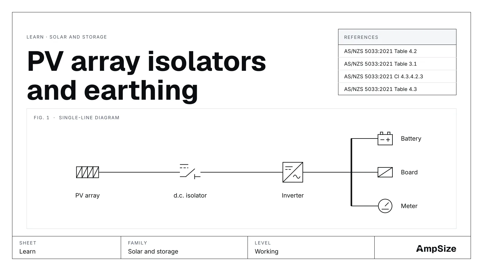
The PV string tool sets the modules in a string and the maximum voltage. The PV isolator and earthing calculator takes that voltage and finishes the array: the cable currents, the d.c. isolator and the earth.
Why parallel strings feed a fault
A PV module is a current source. You cannot switch it off, and a fault on it stays live in daylight. With several strings in parallel, the healthy strings push current into a faulted one. With four strings, one string can take current from the other three. That current can pass what one module tolerates, so the strings may need fuses.
Table 4.2 and the nearest protection
AS/NZS 5033:2021 Table 4.2 gives the current in each cable. The string cable carries the maximum string current plus the fault current from the other strings. A sub-array or array cable carries the sum of the strings it serves. The values depend on where the nearest protective device sits downstream. A cable past a device carries less fault current than one before it. Table 3.1 checks that a sub-array or array device is rated at least the strings it covers times the maximum string current.
Ithe, Ie and make and break
Three ratings on an isolator data sheet decide the job.
- Ithe is the current the isolator carries without overheating in an enclosure. It falls as the ambient rises. Cl 4.3.4.2.3 reads it at 40 °C indoors or in the shade, and at 60 °C outdoors in the sun.
- Ie is the current it switches in normal use, with the poles in series, at the array maximum voltage.
- Make and break is the current it can close onto and open in a fault.
The voltage rating must be at least the array maximum voltage (Cl 4.3.4.1).
Separated and non‑separated inverters
A transformer based inverter is separated. Its d.c. side does not connect to the grid. Table 4.4 lets the poles in series share the voltage, and the make and break rating applies to the poles together.
A transformerless inverter is non‑separated. A fault from one d.c. conductor to earth can leave one pole carrying the whole voltage. So each pole must break the full current alone (Table 4.3). The same applies to a separated inverter with a functionally earthed array. Read the per-pole figure on the data sheet. A rating for the poles in series does not meet it.
The hot isolator in the sun
An isolator on a roof edge runs far hotter than one in a switchboard. Sun on a dark enclosure adds to the air temperature. A data sheet usually states Ithe at 40 °C. At 60 °C it is lower. Check that the de-rated figure still covers the array current.
Enclosures outdoors
Table 4.5 sets the enclosure. A dedicated switch goes in the enclosure it was tested with. A circuit-breaker, or an assembly with other devices, goes in an assembly to IEC 61439. An outdoor enclosure breathes as it heats and cools, and it can draw in moisture. Cl 4.4.6.2 calls for a pressure equalisation valve, or a gland or drain with one nearby.
The earthing path
Above 35 V, Figure 4.13 sets the frame earthing. Frames are bonded together and to the installation earth. A frame earthed for lightning protection takes 16 mm². Where the array is not on an earth referenced system, a 4 mm² bond joins the exposed parts. A separated inverter takes the least size, 4 mm². For a non‑separated inverter, the Table 4.6 columns point to AS/NZS 3000 Table 5.1. That table gives the earth for the inverter a.c. active, or for the array d.c. cable if there is protection. The result is never less than 4 mm². Keep the resistance to the installation earth at 0.5 Ω or less (Cl 4.6.5).
Functional earthing and the alarm
Some arrays earth one pole on purpose. Resistive earthing uses a resistor. Direct earthing uses a solid link, and Table 3.2 gives an earth fault interrupter setting by array power. Direct earthing is under review, so use resistive earthing where you can. Cl 3.5.3 adds an earth fault alarm when the array is above 120 V, or when the inverter is non‑separated.
Next steps
The tool gives the currents but not the conductor. Size the cables with the DC cable size calculator. A worked check is in DC isolator rating for a 10 kW solar array.