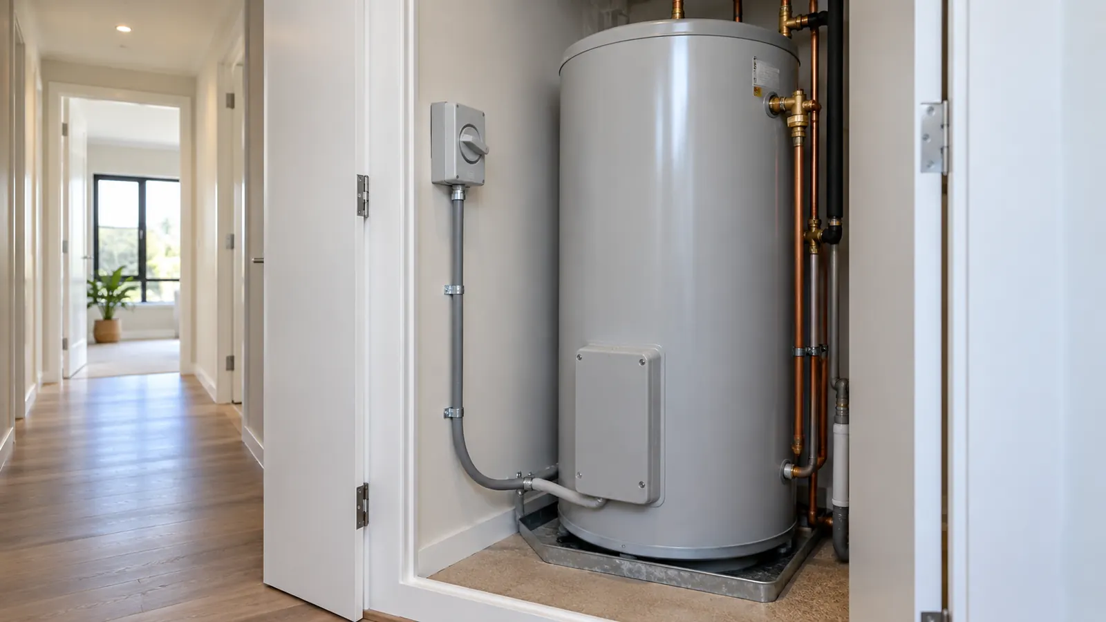
A hot water cylinder is a steady resistive load on a dedicated circuit. The current is short of 16 A and the run is short, so the size looks obvious. The insulation the cable passes through changes the answer.
The question
A 3 kW element on a 230 V single‑phase circuit draws close to 16 A. The circuit runs 20 m from the switchboard, partly surrounded by thermal insulation. The space reaches 35 °C. A 16 A C curve breaker protects it and the external loop impedance is 0.35 Ω. The tool reports the size that passes every check.
The inputs
- Phases: 1
- Voltage: 230 V
- Design current: 16 A
- Run length: 20 m
- Installation method: partly surrounded by thermal insulation
- Wiring enclosure: none
- Ambient temperature: 35 °C
- Protective device: C curve, 16 A
- External loop impedance Ze: 0.35 Ω
The hot water load sits in group F of Table C1 in AS/NZS 3000:2018 for the maximum demand assessment. That group is separate from the general socket‑outlet groups. The cylinder does not change the socket allowance on the mains.
The clauses
Cl 3.4 of AS/NZS 3000:2018 sets the current carrying capacity requirement. Cl 3.6.2 sets the voltage drop limit. Tables 4 to 21 of AS/NZS 3008.1.2:2017 give the tabulated current ratings, and Table 22 gives the grouping factors. The ambient factors come from Table 27.
The steps
The tool derates first, then tests every standard size.
The ambient factor at 35 °C is 0.94. The circuit runs on its own, so the grouping factor is 1. The route is not buried, so the soil and depth factors are also 1. The total derating factor is 0.94.
Dividing 16 A by 0.94 gives the required tabulated current: 17.02 A. The tool then looks for the smallest size whose tabulated rating reaches that figure.
The result
The answer is 2.5 mm².
- Derated capacity: 17.86 A
- Voltage drop: 2.27 %
- Device rating: 16 A
- Earth fault loop impedance: 0.71 Ω
- Earth conductor: 2.5 mm²
The circuit passes all four checks. 17.86 A of derated capacity covers the 16 A design current. It also sits above the 16 A device rating, as Cl 2.5.3.1 requires. The drop of 2.27 % is well inside the 5 % limit. The Zs of 0.71 Ω is inside the Table 8.1 limit for a 16 A C curve device.
Which check sets the size
The candidate list is where the reason shows. 1.5 mm² gives a voltage drop of 4.15 %, so it passes the drop check. It carries 13.16 A after derating, so it fails the capacity check. It fails the device check against the 16 A breaker as well.
Capacity therefore sets the size on this circuit, not drop. That order reverses on a long run. Drop then sets the size, and the tool returns a larger conductor for that reason alone.
The insulation is the input to get right
The installation method changes the tabulated rating more than the ambient temperature does. A cable clipped in free air carries more than the same cable in insulation. Full enclosure in insulation lowers the rating further. A batt pushed over a cable after the sheet is fixed changes the installation method. Nobody enters that change into the calculation.
Check the route on site and pick the method that matches the worst section. The tool applies one method to the whole run, so the tightest part governs.
This page is a design aid. Verify every value against the current edition of the standard.
See also: Cable size for a 20 A heat pump circuit in summer, Cable size for a 32 A single‑phase 25 m run and Current-carrying capacity and derating.