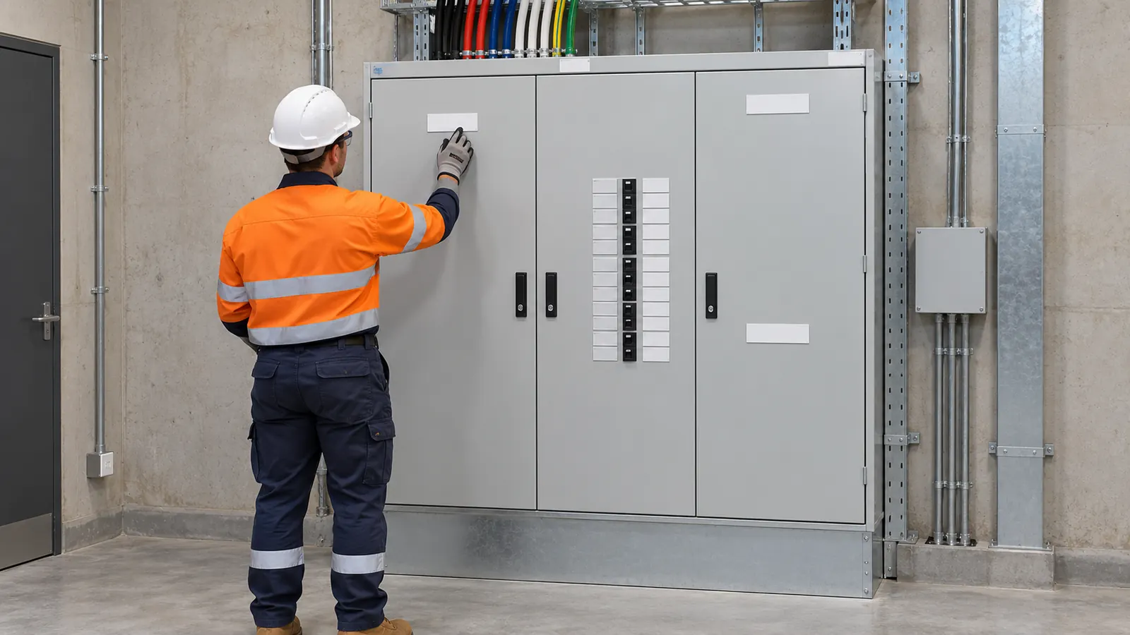
An arc flash label carries three numbers: the incident energy, the boundary distance and the PPE category. This page works one commercial main switchboard through to those three numbers.
A common assumption is that a lower fault current gives a safe result. A commercial board fed through a long service often sits near 12 kA. The upstream device is slower than a downstream breaker, so the clearing time grows. Energy is the product of power and time, so the result stays high.
The inputs
The case is a 400 V main switchboard in a commercial building.
- System voltage: 0.4 kV
- Bolted fault current: 12 kA
- Clearing time: 0.3 s
- Equipment: switchgear
- Enclosed: yes
- Earthed: yes
- Working distance: 600 mm
The working distance is 600 mm rather than the 455 mm default. That suits a person standing at the front of a floor-mounted board with the escutcheon off.
The model and the clauses
The tool uses the empirical model of IEEE 1584-2002. Cl 5.2 covers the arcing current. Cl 5.5 covers the arc flash boundary. The tool now opens on the 2018 model. The example here keeps 2002.
AS/NZS 3000:2018 Cl 2.5.5 covers arcing fault protection in an installation. It does not set a label format. The label content follows the study, the site rules and the employer safety system.
The steps
The equipment type sets the electrode gap. Switchgear gives a gap of 32 mm.
The bolted fault current and the gap give the arcing current: 6.44 kA. Arcing current is always lower than bolted fault current at 400 V. That matters, because the upstream device sees the arcing current, not the bolted value.
The arcing current and the clearing time give a normalised incident energy of 1.745. The tool then applies the enclosed and earthed constants as a calculation factor of 1.5. The distance exponent for this equipment type is 1.473. It scales the energy from the normalising distance out to 600 mm.
The result
- Incident energy at 600 mm: 4.02 cal/cm²
- Arc flash boundary: 1,368.01 mm
- PPE category: 2
4.02 cal/cm² sits just over the category 2 band edge of 4. A small change in clearing time moves this case across that edge. Halve the clearing time and the energy falls with it. Add a second device delay and the category rises.
The boundary of 1,368.01 mm is where the energy falls to the onset of a second degree burn. It is wider than the front of the board and wider than most switchroom aisles. Plan the approach and the barrier position from that figure, not from the panel depth.
Two inputs carry the result: the bolted fault current and the clearing time. Get the fault current from the transformer calculator or a network study. Get the clearing time from the upstream protection setting that actually clears a fault at this board. Do not use the downstream breaker time.
The equipment setting also matters. Switchgear, an MCC and a cable junction box each carry a different electrode gap and distance exponent. Change the equipment type and the energy changes. The fault current and the time can stay the same.
The enclosed and earthed toggles apply the calculation factor of 1.5. An open air arc at the same current gives a lower energy at the same distance. An enclosure directs the arc products towards the worker.
The result on this page covers one point in the installation. A study covers every board and every work position. Each one has its own fault current, its own clearing time and its own label.
This page is a design aid. Verify every value against the current edition of the standard.
See also: Arc flash incident energy at a 400 V switchboard, IEEE 1584-2002: arc flash model and limits and Arc flash basics.